“You have a quite novel approach to high current circuits”
(This is one in a series of posts, not in chronological order.)
Lately I’ve been playing again with switched supplies. The last time I worked mostly blind, not having a scope I sampled the available inductors around my needed values and settled with the ones that didn’t catch fire for the first test run.
Now I wanted to try more topologies, and having a lot of unknown cores, I needed to characterize them. I started with the traditional BH measurement using a small ac source and an integrator. I haven’t got round to finish the writeup on that one but it gave me some useful data to start.
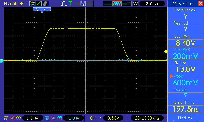
Still, I needed to measure with more precision their inductance and how they behave when handling high currents. I lashed up a pulse generator with variable on period using a couple of schmit trigger gates and a level shifter. When loaded by the gate the risetime goes from about 20ns to 200ns, there’s room for improvement considering it was made from parts I had lying around and without too much thought. I can also lower the drive voltage, above 6 volts the gate charge increases. Meanwhile, I’ll need to add an isolated trigger output.
-

- Pulse generator output. No load.

-

- Pulse generator output. Loaded.
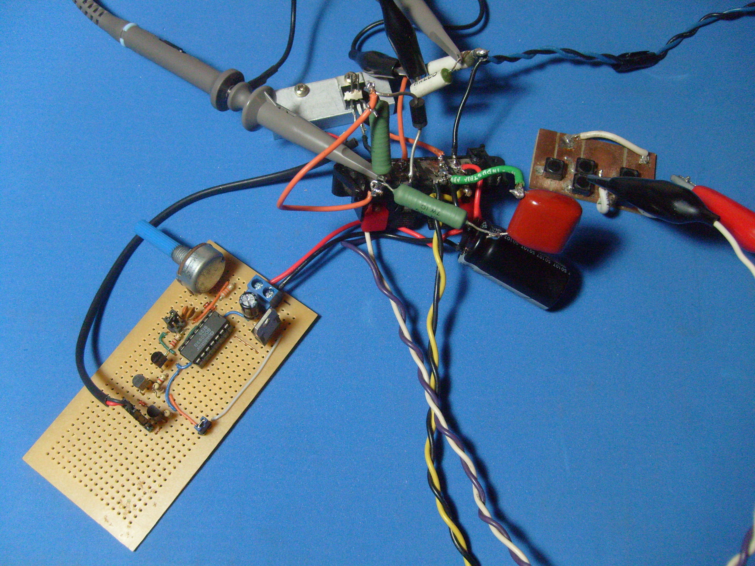
The power section is comprised of an irf540, a medium value shunt, flyback diode, some local decoupling and a snubber. I’m using high side sensing as it lets me monitor the current and voltage on the dut easily without resorting to differential probes. Also the fet’s source won’t rise above ground when using the same supply for both the driver and power stage, sparing me from a whole lot of problems. The shunt is made with two 0.22 ohm resistors of dubious quality in parallel. While I have a couple of 50 mohm ones made just for that for most of the time the resulting voltage will be too low to work comfortably. It doesn’t look good but gets the job done (the power section was made with parts from another test fixture, so there are some leftovers).
Shorting the test leads I get this:
-

- Test leads shorted. Yellow: current / 9.11 [Amps] . Blue: voltage at binding posts.

-

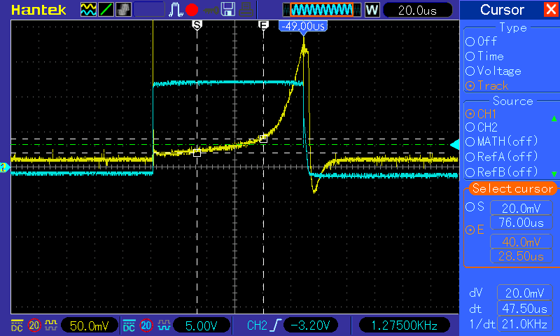
- Test leads shorted. Yellow: gate drive. Blue: Vcc.

Plugging in all the constants the fixture has a stray inductance of about 2.1 uH. ( V/L = dI / dT , all that can be read off the cursors ). On the linear part, the average current is 25 amps, so the resistance turns out to be close to 0.4 ohms. Looking at the power input it dips around 2 volts (not that bad being it a cheap pc supply) and then overshoots by 6 volts. However, looking at the connectors on the far end it is not that bad:
-

- Blue: vcc at power supply. Yellow: gate drive (see below).

So, most of the voltage drop and artefacts are due to poor local decoupling, long leads and connector resistance. That funny ringing on the drive signal is because the scope ground is just at the supply terminals and it bounces a lot given that there are about 30cm of leads in between.
After tidying things a bit and putting the snubber and flyback where they are supposed to be it works like a charm:
-

- Testing a transformer.
Redid some of the shots, so their dates don’t match anymore.
[…] « Inductor saturation tester […]
[…] the datasheet only shows a 100nF on the output. Not that it really matters on this case. On the pulse generator the logic gates are fed from a regulated supply, mostly so I can forget and use the same as the […]