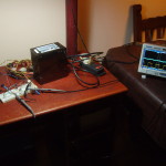
So last week I gifted myself an arm linux system with a very fast soundcard. Or a 100MHz digital oscilloscope, as they are quite the same.
A while ago I made a current sink that has served me well for testing dumb power supplies and anodizing stuff. For mostly resistive loads it behaves well, however as soon as you try to load something with small resistance and some inductance (like the head coils of an IBM3390 disk or a very stiff smps without a resistor to dissipate most of the power) it starts to oscillate.
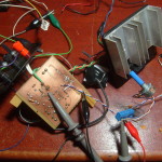
Possessing this new gadget and a cold I decided to spend the weekend tackling this problem. I started by making another one on a breadboard and feeding back the current sense with a four terminal setup. That was quite an improvement over the original, among many mistakes I used a ground pour and despite the high current loop being very small and near the binding posts the ground potential differed by a not insignificant amount between points on the board.
The only power supply I had was a not very bad ATX one from a former desktop. It’s beefy and I can attest that the current limit and short circuit protections do work. The only downside is that it is really noisy, about 100mV p-p on the 12V rail with a 2A load and it gets worse from there, mostly from the conmutation and some hf hash. So the first thing I did was to improvise a couple of regulators with a low pass filter and a series pass transistor. After that it went down to 2mV p-p, rejection is not that great but will do.
My initial intentions were to approach the problem from a control system point but even for a quite trivial circuit like this one the modelling becomes convoluted once you add stuff like the feedback from collector to base on the output transistor, the dependence of the small signal gain and CE capacitance with the operating point or the interactions between power supplies. And most of them have influence on the oscillatory behaviour with extreme loads.
So I gave a full turn and started with a more practical solution. One of the first things to improve stability is to reduce gain or at least roll off at high frequencies. I replaced the original feedback loop with a 10K pot, wiper goes to the inverting input, one side to the opamp output with a 100n cap and the other to the sense resistor. Then, with a problematic inductor, I slowly rised the current setpoint until it started to oscillate; moving the wiper closer to the output made it stop. This has to be repeated a couple of times, as there are many unstable points. The only drawback of this approach is that the corner frequecy is fixed and you only end up changing the gain, and as such there can still be a lot of unstable operation points.
After that I continued by adding a snubber network from ground to the collector, effectively bypassing the control loop. There are many recipes for when you know with more or less accuracy the parameters of the tank circuit but in this case all I knew was that the output capacitance of the TIP122 was on the order of 200p and most of the things I am interested on have inductances from some uH to many mH. I had a 1uF mica and a 2.7Ohm power resistor at hand and gave them a go. Bam! all the oscillations were gone.
But what happened to the dynamic response of the system?
The snubber network had no visible effect. On the other hand the naive compensation worsened the disturbance rejection. The arrangement with a potentiometer has the side effect of behaving like a low pass filter for the signal that comes from the sense resistor, thus increasing the response time, as can be seen on the following pictures (the glitchy stuff is because I just shorted the load with an alligator clip).
While I’m mostly happy because the dummy load has improved I still feel like a hack because solving the problem from a more analytical standpoint turned out to be more difficult than what I expected. However, if I consider that I made every possible mistake on the initial design and this testbench stabilizing it was quite a feat (just a copper pour for the groundplane, power and signal grounds mixed, loops, long cables, etc).
So far I made three mathematical models that kind of satisfy me but every one explains part of the observed behaviour and involve some unnerving hand waving and simplifications. I will upload them soon.


