A couple of days ago I started to learn FreeCAD, mostly for its FEM analysis mode and to build a couple of construction plans.
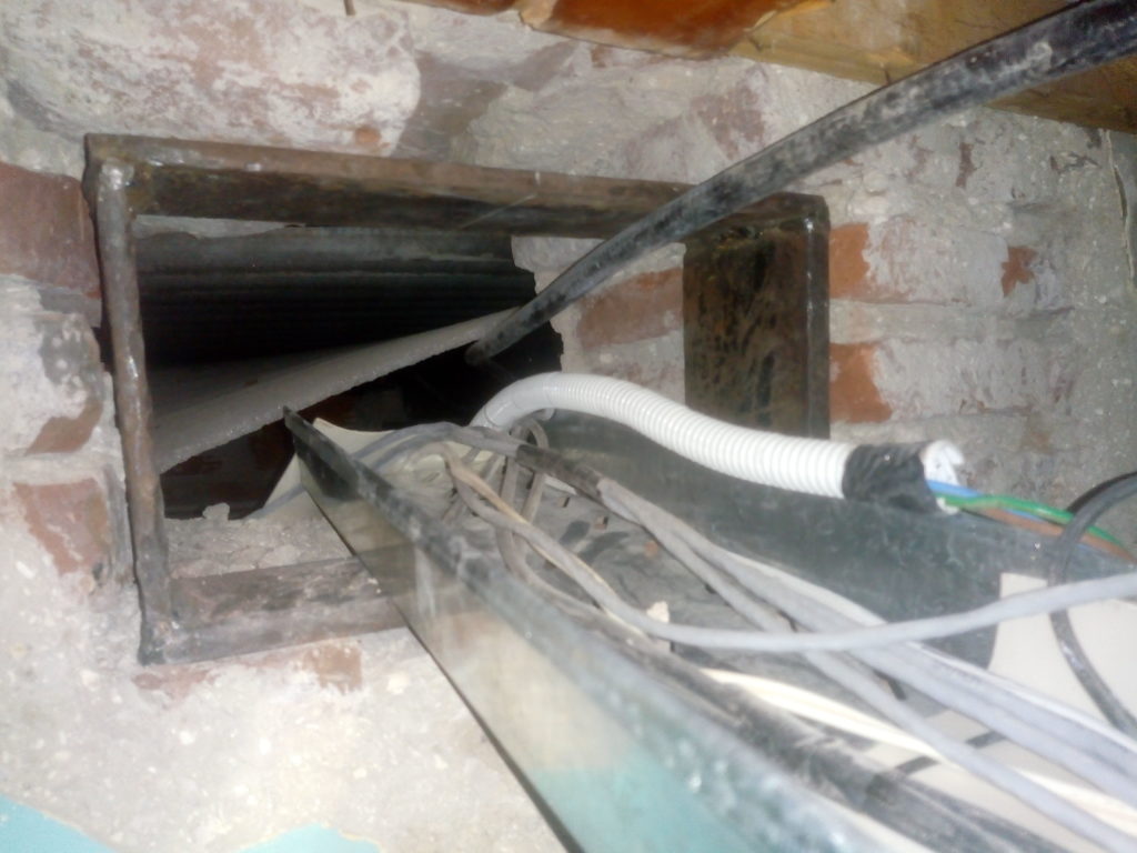
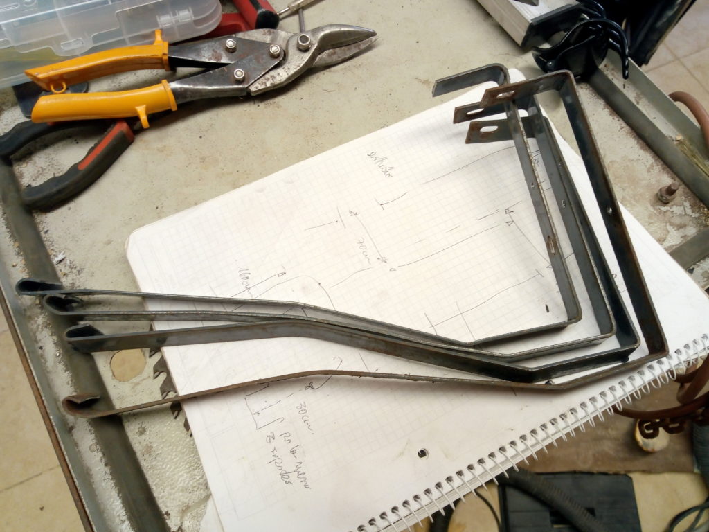
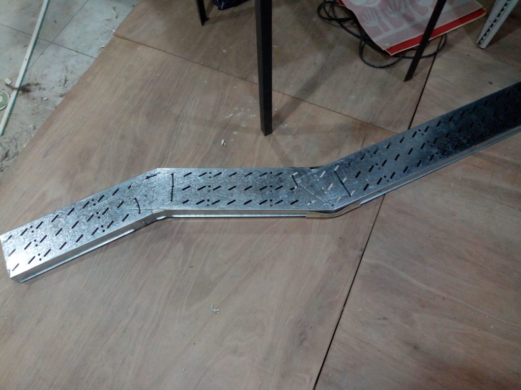
I made another part of the cable trays for our comms closet. Initially I wanted to use FreeCAD for that but at the end it was faster to do a bit of trig and sketch the cuts on paper. It’s held in place with a couple of rivets. I also added a layer of pvc to shield the cables from the metal edges. Fits like a glove.
Cable tray bend
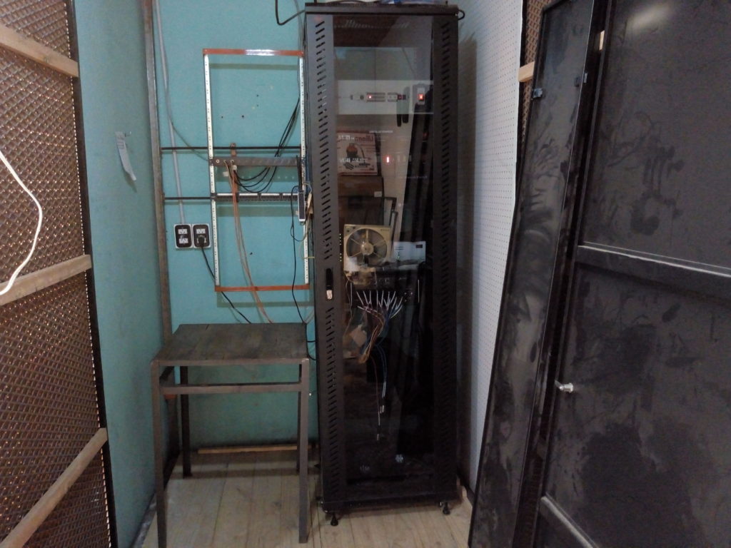
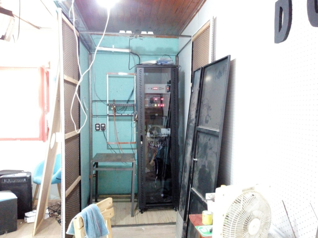
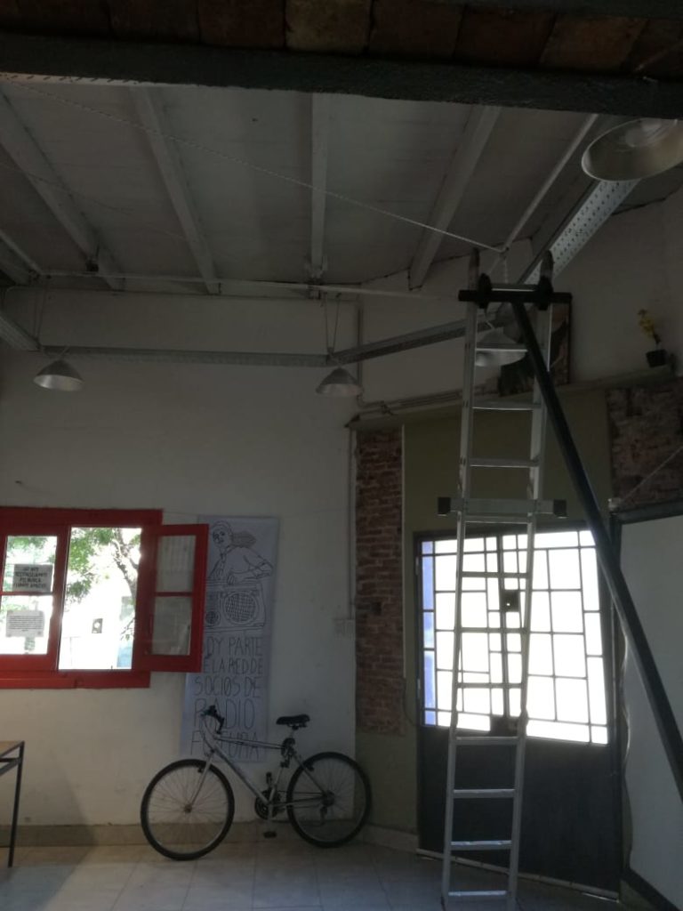
I also started to build a steel support for one of the walls. We made a big opening for cables and I’m a bit uneasy about the lack of support.
These doors were waiting a long time to be installed. Now this looks a bit more professional than before, except that on the opposite side there’s a chunk of wall missing and a lot of dust on the new hole to feed another cable tray.
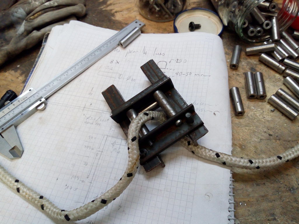
Today I started to build the rope guides for the lightning fixture. I have some nice ground rods from a textile machine that are perfect for this.
Rope guide with rollers
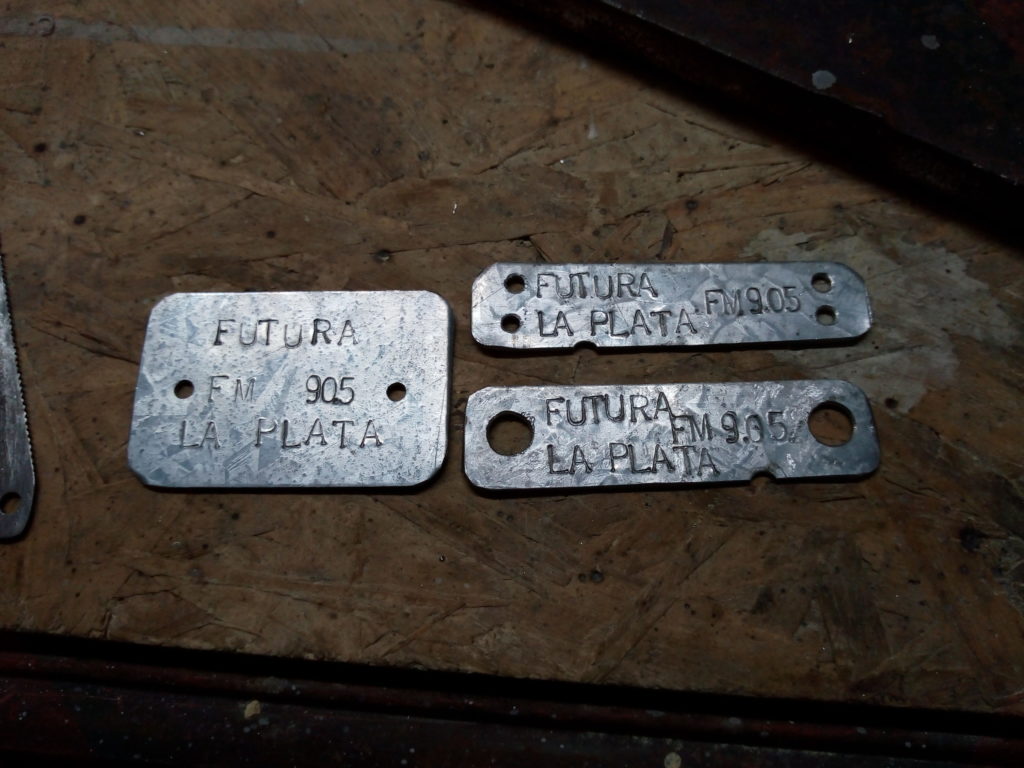
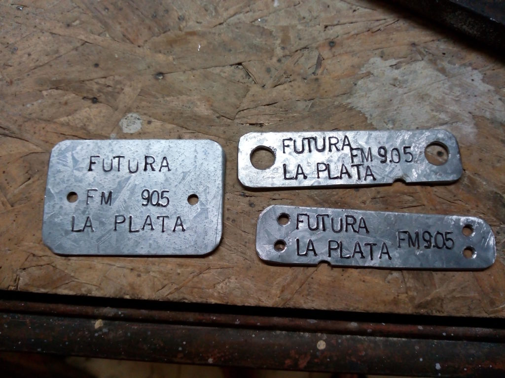
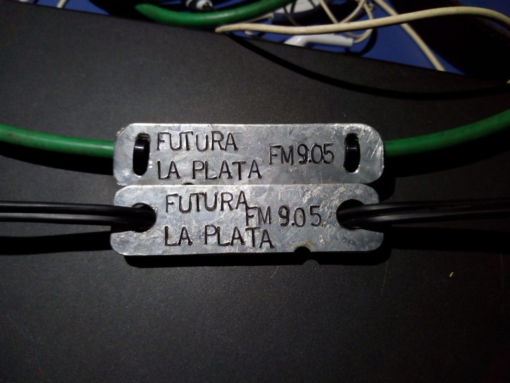
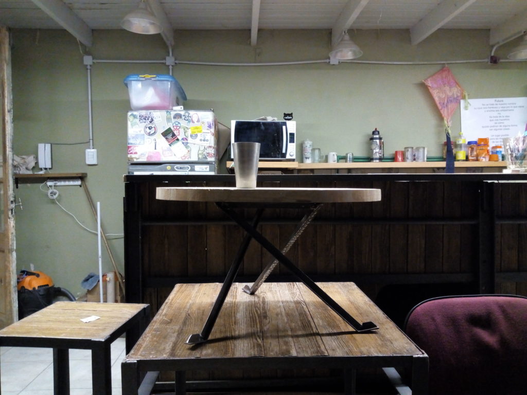
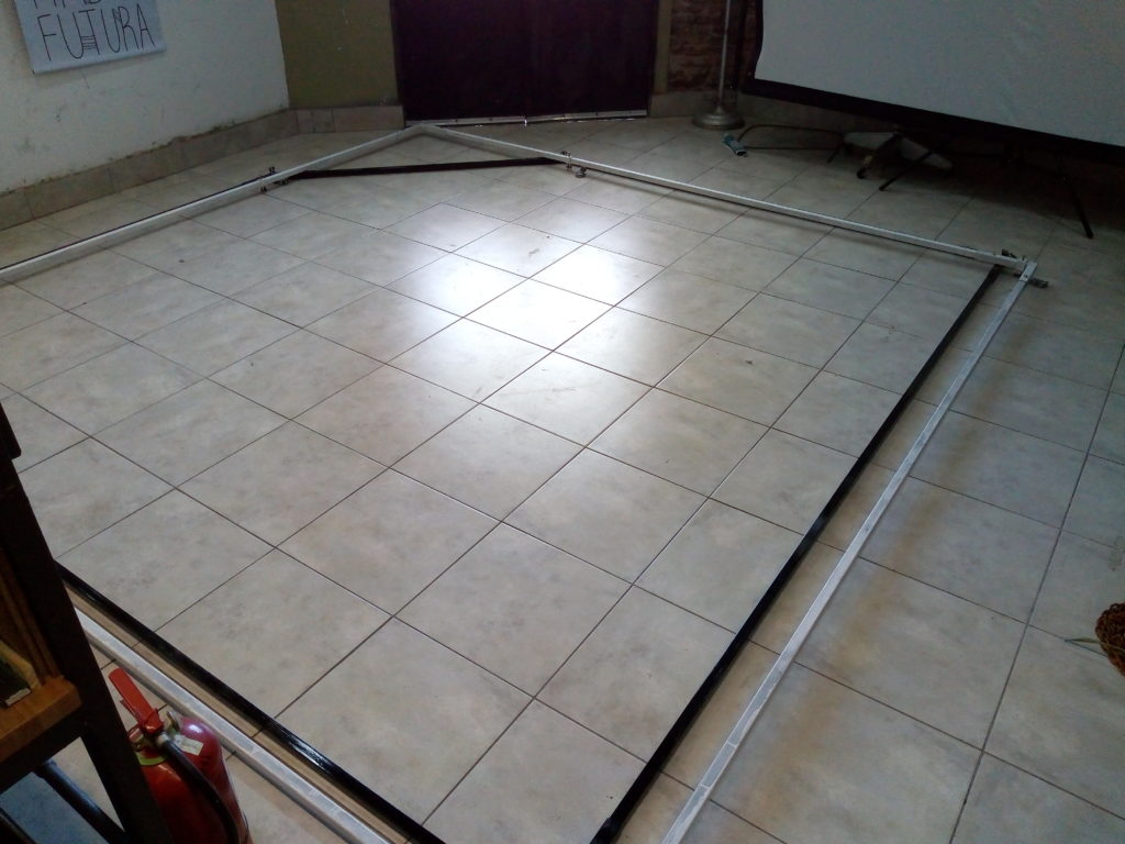
On the evening I went to Futura and cleaned up a bit the stage, moving most of it to one place:
The Museum Corner at Futura
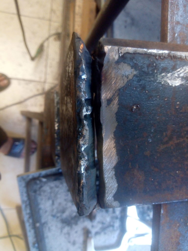
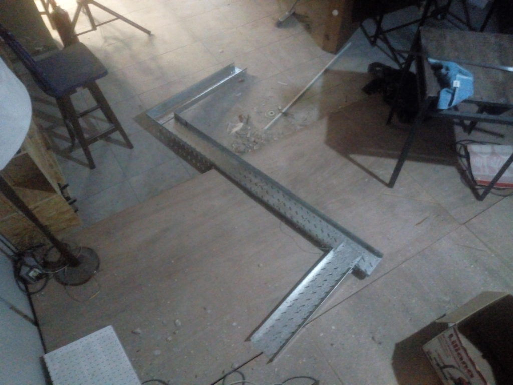
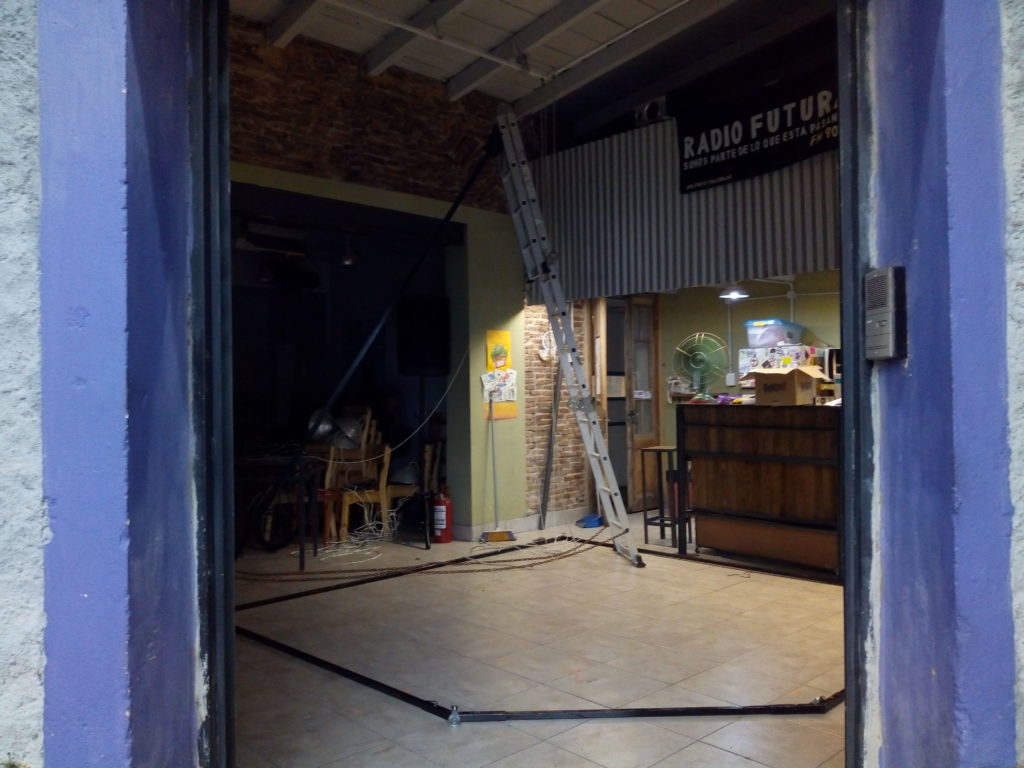
Then I started to install real cable trays instead of our improvised version with halves of water pipes. I need to cut a small section with a special bend to accommodate the opening on the wall.
Cable trays
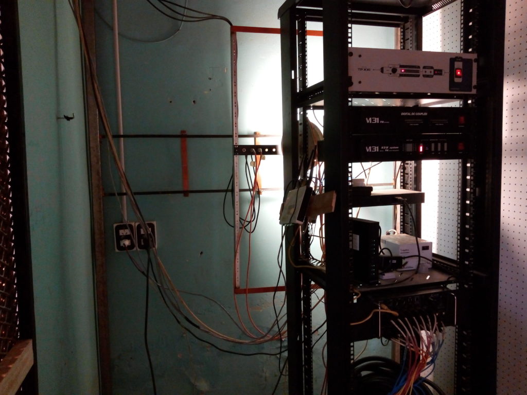
I emptied most of the rack cabinet and installed the patchbay I built earlier. I had to drill and tap another set of holes as the power outlet interfered with the movement.
We have this old scope for the students. It’s been unused for a while as it behaved erratically and then stopped working completely.
After setting the trigger to a more or less sane value I had something on the screen but the controls where flaky. A heavy dose of our deoxit equivalent and twisting it sprang to life. I adjusted the dc offset (drifts a bit while warming up) and matched the channel gains as much as I could and called it a day.
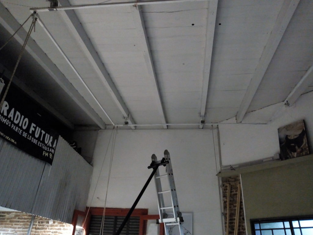
At least for now. The next step will be adding another support for the roof frame and rollers to guide the ropes around it to unblock the light path should we want to project from there.
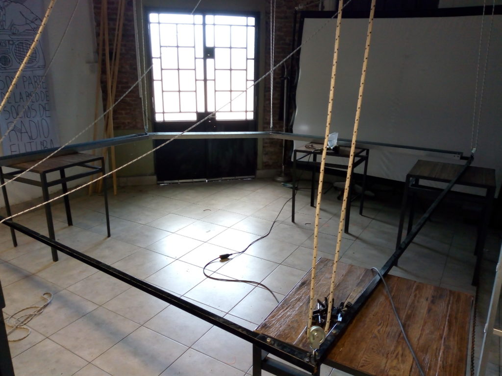
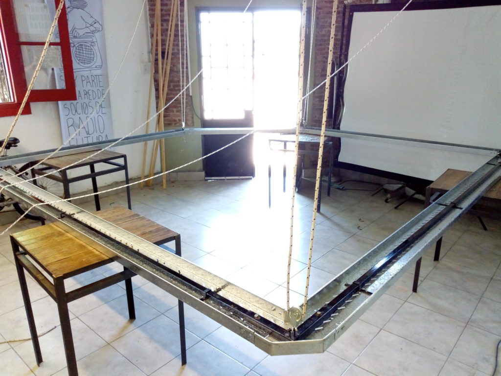
Today I hanged the lower frame and then attached the cable trays with a set of bespokeclamps and self tapping screws.
Lamp fixture: all frames linked, attaching the cable trays
Our original plan was to install some cable trays to have a more industrial look.
Yesterday I assembled the frames on the floor:
Lamp fixture: metal frames
Today I spent most of the afternoon drilling the wood trusses on the roof and attaching the hooks. Then came the time to lower the old frame and hang the white on those hooks.
Letting it gently go down was easy:
Lamp fixture: dismantling the old one
I used some wire to attach the new frame to the old pulleys and help me lifting it near the roof. That seemed a lot easier on the planning stage but I managed to pull it off in a couple of hours.
To end this day I wound the new rope on the pulleys. Tomorrow I’ll hang the other frame (the black) and screw the trays to it.
We have a discrete, and new, metal door but the inner handle is one that was in the house since the 1950’s.
On the outside there’s just a simple knob but it’s not linked to the lock. The handle works as intended but if we are not careful when pulling we end up with it on our hands.
I made a simple plate and kept the rod in place with an M4 screw threaded through it.
It served us well for a long time, however it was lost when we moved to a new location.
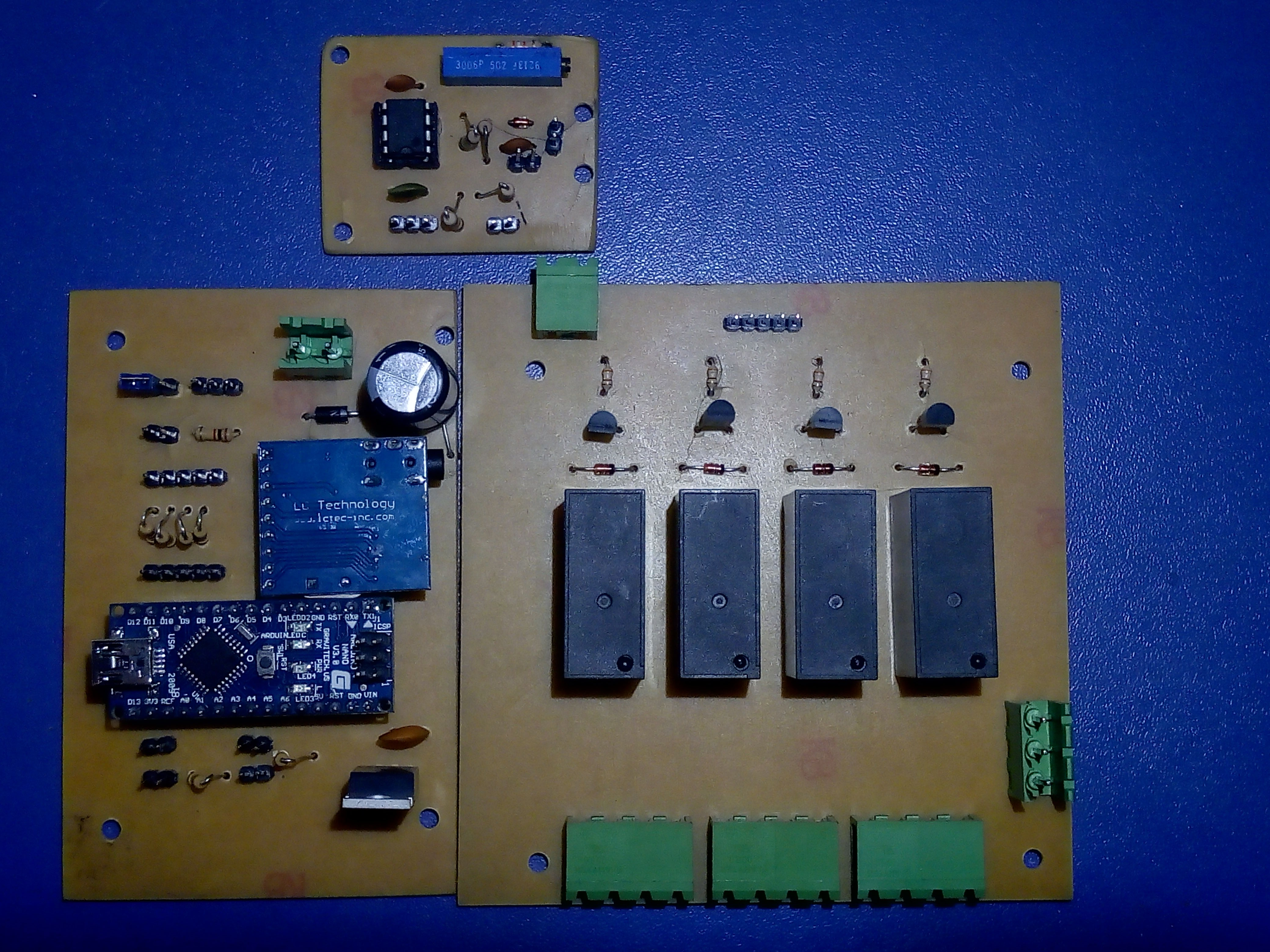
For the last couple of weeks I spent a while polishing the firmware and making new boards in KiCad. The original was very crude, just a simple on/off panel and delayed power sequence.
This one adds an RF sense and automatic restart, so if one of our amplifiers bails out on a power dropout we don’t have to do anything about it.
Yesterday I etched the boards. I ran out of toner and had to ask a friend to print the transfers. They came horrible but work fine nevertheless.
It’s amazing that nowadays buying an arduino and a preassembled dtmf decoder is cheaper than the single chips (and not counting the time to layout a more complex board).
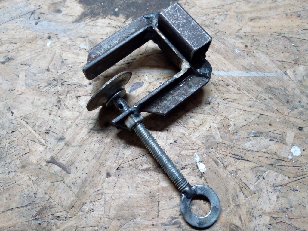
Here at the Uni lab we have a nice articulated lamp that lacks a base. It’s been sitting on a corner for ages so I set to make a new clamp for it.
The frame is just a bit of T beam with a nut and some square tubes welded.
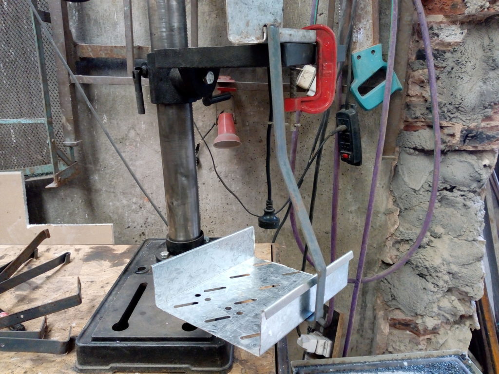
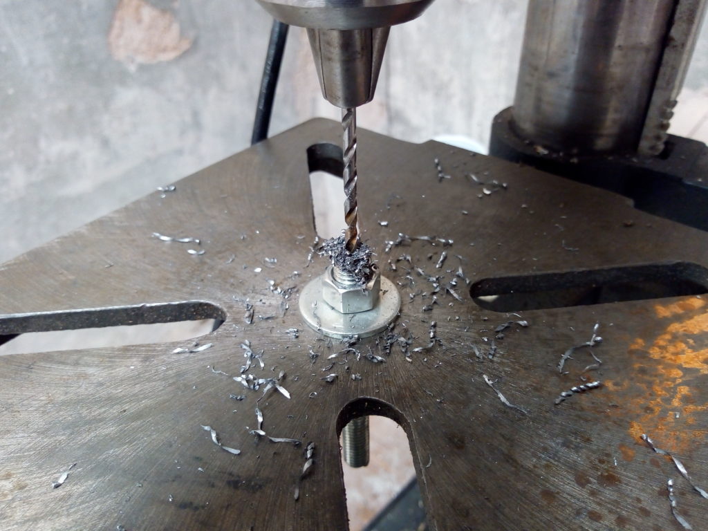
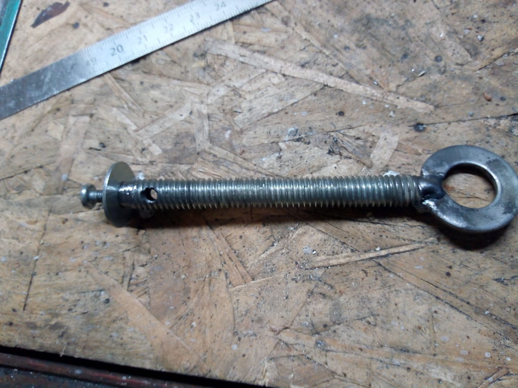
For the handle I used a bit of 3/8 threaded rod and a big washer I had lying around. In order to fix it I decided to make a hole along the axis and tap it to M3. After center punching the rod I screwed it to the drill press, using a center drill to align it. The plan was foiled when I tried to drill, as I left the base loose and it moved. But it’s good enough.
Homemade C clamp: drilling a threaded rod
Homemade C clamp: drilling a threaded rod
My initial idea was to use another nut and a locking pin behind the front washer but that used up a loot of the available space inside the clamp. After a bit of head scratching I ground a small taper and added a small washer to push the bigger one instead of a nut. I’m quite proud of how it turned out.
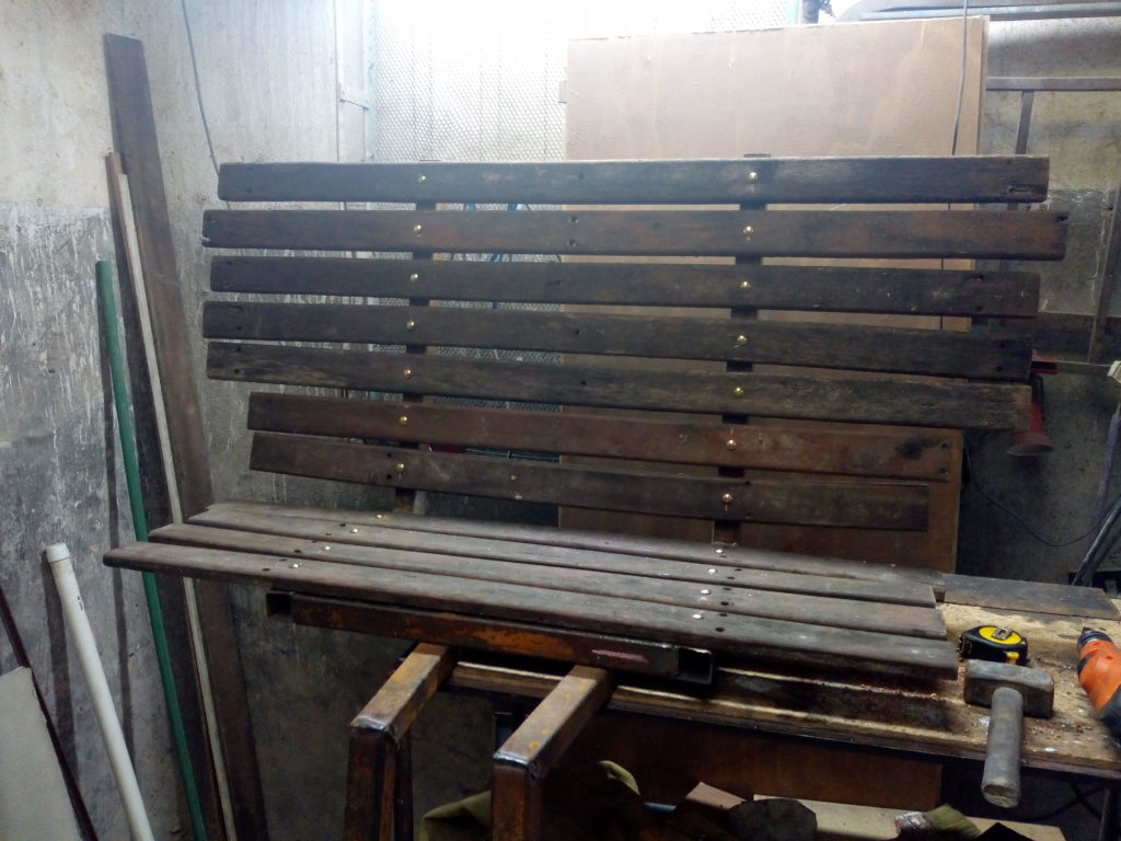
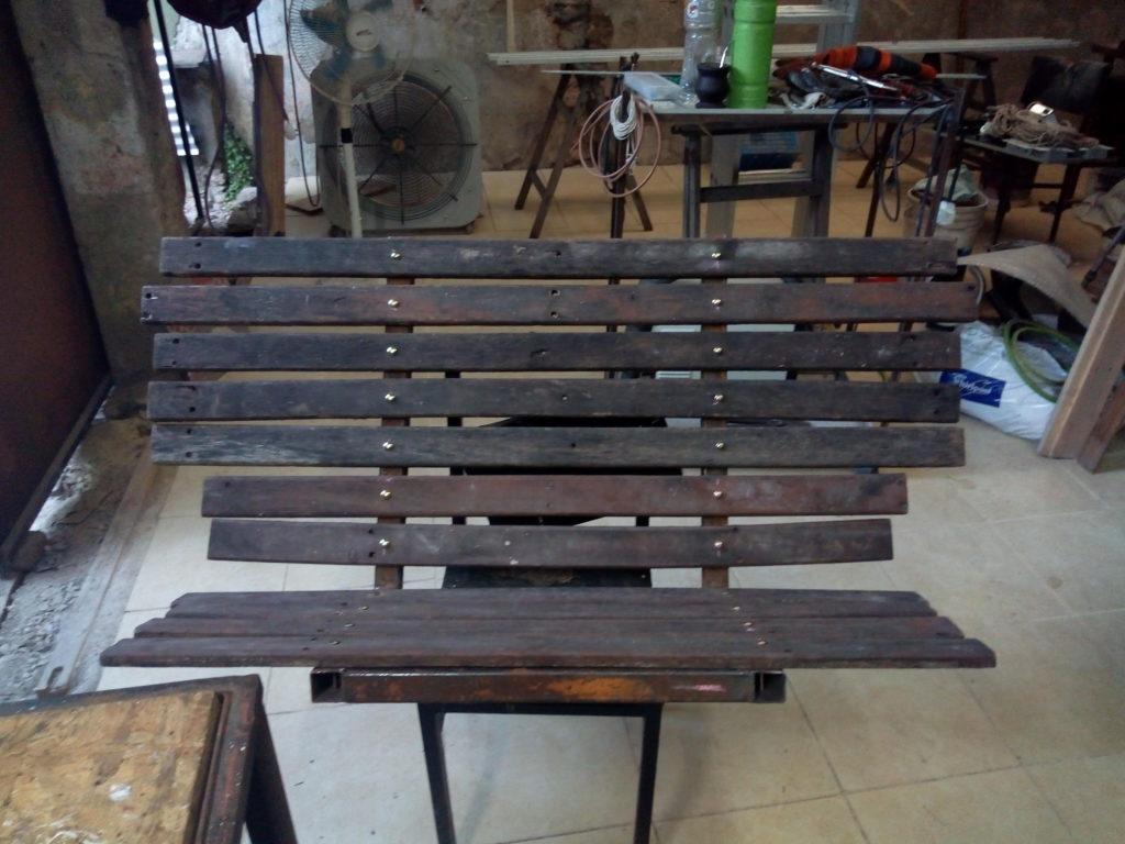
A while ago we were given a bunch of weathered wood from a deck. Some of us have been thinking of installing seats on the sidewalk and this looked like a good opportunity.
I built a simple frame with square tubing and used one of the wood packs to try it out. I need to select the best planks but it’s comfy and with a bit of paint will look good.
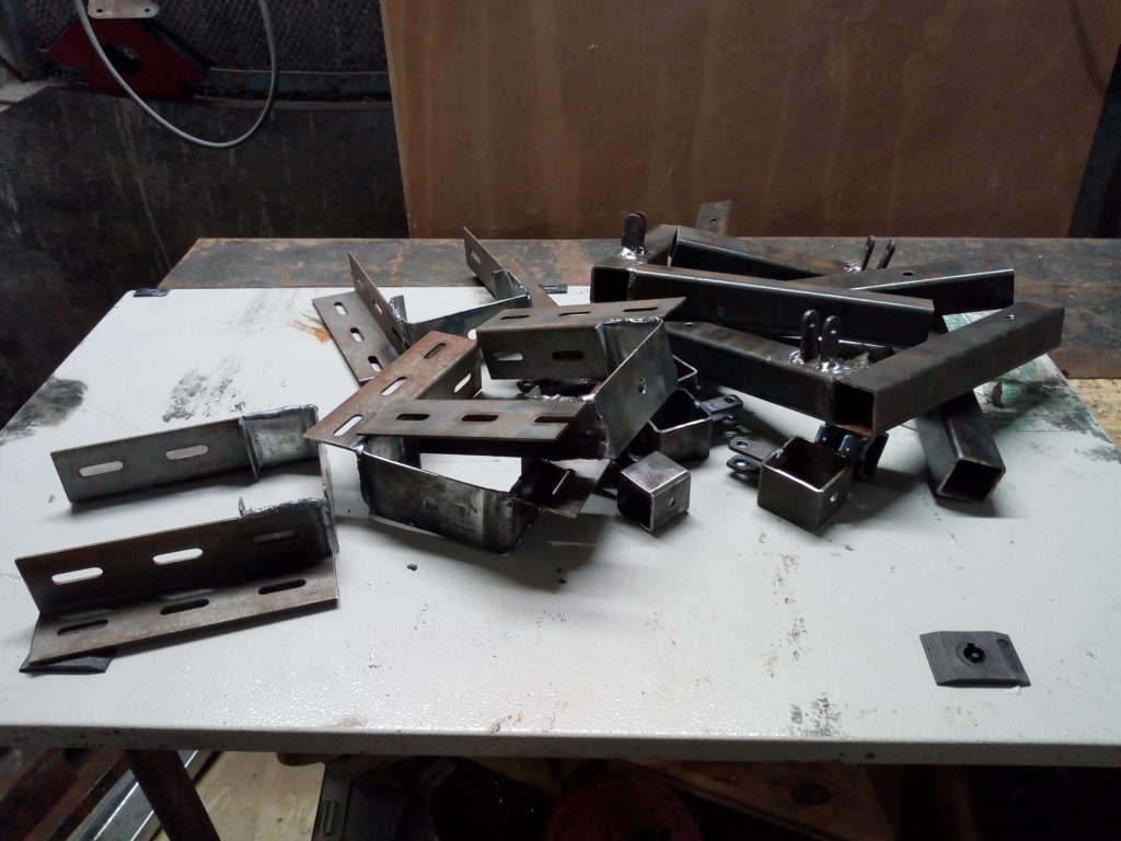
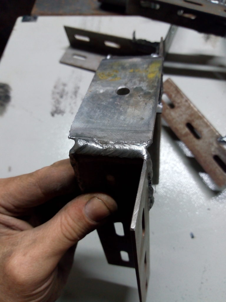
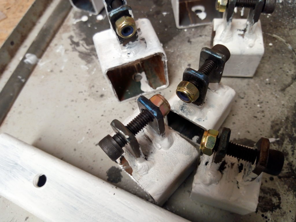
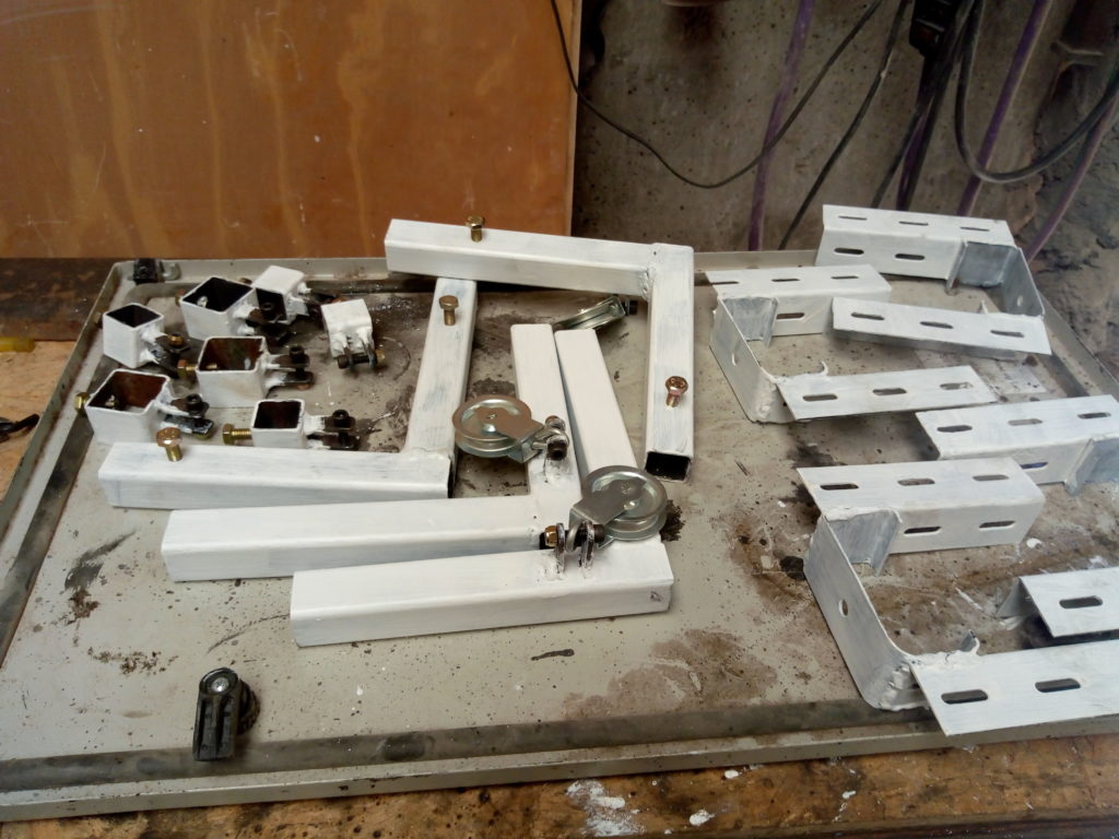
The last two days I finished the welds on those clamps, built some to hold the other end of the ropes and four sturdier to screw to the roof trusses. All the screws are paired with either a nylock or two nuts locked to each other.
I painted the pieces for the bottom frame with black enamel and the ones for the roof with white to match the rest of the room. I know they’ll rust in some weeks but I left the blued surface exposed. I never tire of looking at them.