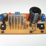
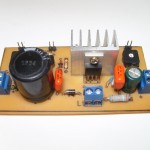
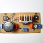
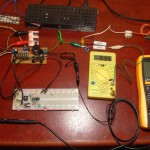
A while ago while cleaning the trash pile I thought that it’d be nice to mod one of the many computer supplies to have a variable output. So I picked up the less crappy, replaced the transformer with a one with better turns ratio to achieve a higher voltage output and put a pot on the feedback loop.
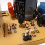
At first it kind of worked but with a lot of unstable points and weird modes. Then I realized that I fed the feedback from about 50K when the nominal was near 10K (and also there is considerable input current there). A simple emitter follower took care of that, now there only remains plain oscillations.
The operating point moves a lot considering that I want the output to be adjustable between 5V and 50V and without a fixed load. The original compensation scheme was a plain integrator plus a zero, I can make things a little better slowing it down a lot but what’s the fun on that.
So instead of blindingly doing things I set out to measure the loop response using Middlebrook’s method. I cobbled up a quick python program with Gtk and GStreamer to generate the test signals with a computer soundcard. Initially I expected to just sweep the frequency and measure some points manually on the scope but there is a lot of 50Hz induced interference that together with switching residuals make that task impossible, I really need to perform a synchronous detection in order to get a meaningful result. That means I’ll have to make room for some more quality time coding to get the scope samples in an automated fashion. The usb protocol is documented here ( http://elinux.org/Das_Oszi_Protocol#0x02_Read_sample_data ).
The setup is a far cry from the ones depicted in the famous AN70 by Jim Williams. I used an H-Field probe to rule out magnetics as an interference source. I expected the output filters and the transformer to be troublesome but their effects on the point of injection are negligible. On the other hand, long wires on the feedback path (even twisted) and the snap recovery diodes aren’t a good match.
- Measuring loop response with the Middlebrook method using a computer and an audio transformer.

