Reduce, Reuse Recycle summary December 2017 – January 2018

(Sounds nicer than saying dumpster diving eh?)

We can learn a lot about a society just from looking what we throw away (see Garbology).

When I lived in Berisso it was really odd to see on the curb something that worked or was fixable.

Here in La Plata and without even trying I stumble upon stuff that is just a little bit broken if not working (albeit a tad old).

This last two months among other things I picked up with my bike basket:

  • A vacuum cleaner, complete with hoses. Only needed a carbon brush replacement.
  • Home audio amplifier. The cd tray is stuck but we feed it from the line in. A bit heavy but very nice sound.
  • Mantle top fan. Works fine as a fan but the pivoting mechanism is acting up. Just needed a thorough cleaning.
  • Leather briefcase. Sold in less than a day as a theater prop.
  • Wooden wine rack. Works fine for other beverages too.

This is not exactly dumpster diving but I also helped the widow of a neighbor silent key to clean up his shop.
Out of the deal I got:

  • Two 100Mbps rackable switches. They work but at that speed I only want them for the chassis and supplies
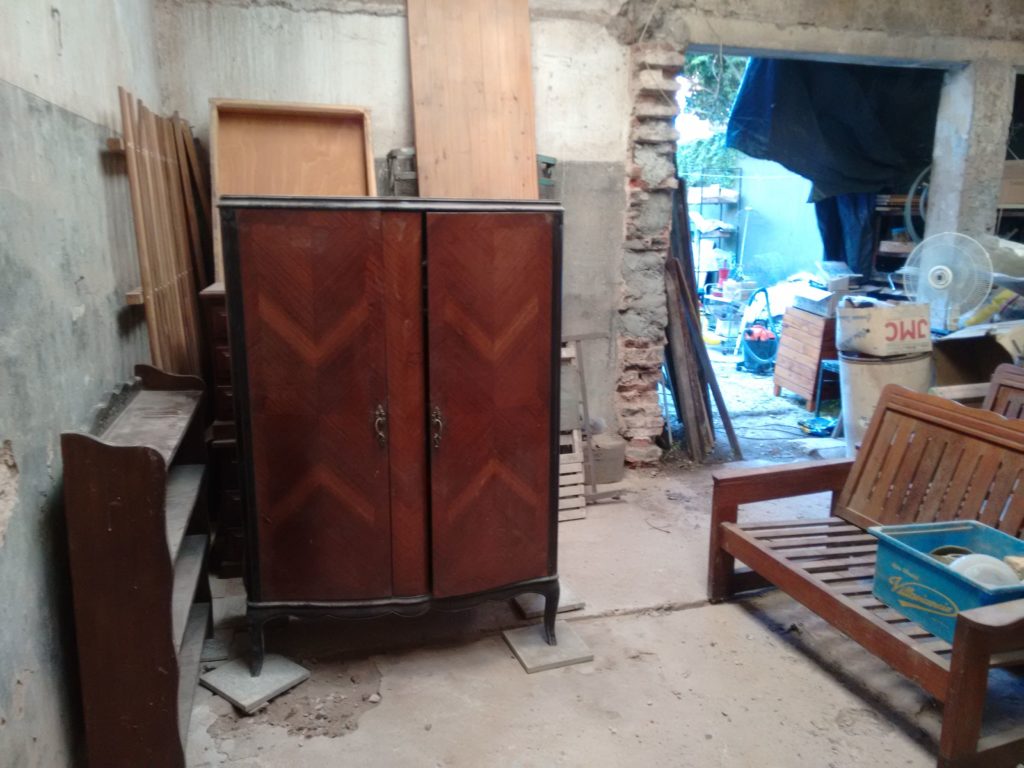
  • An antique lamp. Already restoring it.
  • A Commodore 1541 dirve and some original CompuServe disks. On their way to a museum.
  • A very old (when telegraphs were the norm) glass insulator and threaded pole made of hardwood. Has the right volume to make a shot glass.
  • A modern medium voltage insulator. It’s quite heavy but in nice condition. I’ll probably make a lamp out of it.
  • Lots of heatsinks and coolers.
  • Old cans of candy and medicines. They don’t have a high monetary value but are collectible and can be traded for something else.

Time for cleaning up.

On the back of my current house there’s a shed where my parents dumped most of the stuff that belonged to my grandparents, even a car.

For quite a while I was in need of a personal space to work and store some tools. So earlier in December I started to move things around, give away some stuff and trash the rest.

It’s a pity I didn’t take pictures of the initial state but before this I could only peek from the door.

Looks messy but this is an incredible progress:

Fixing a microwave oven with a broken keypad

This is by far one of the most productive things I did this week outside of work (at least the one I can write about here).

A couple of months ago my ex gave it to me, it started with intermittent display issues and one day it stopped completely. I picked it up and stored it.

The other weekend I was in a bit of cleaning frenzy and I remembered that it was using valuable space on the shack doing nothing so I set to see if it had any hope of working again. Otherwise I’d take the transformer and dish motor, the magnetron would go to a friend and the rest sold as scrap.

This is the second time I fix a microwave oven and I’m amazed at the amount of grease and acid stench that accumulates inside them.

I bridged the safety interlock pads on the control board and powered it with an isolation transformer. It kinda turned on but was not responsive and only some digits were dimly lit. It was also very sticky.

After that I cleaned it using lukewarm water, detergent and a toothbrush, a scoop with a hair drier and then another bath with alcohol.

Now it works!

The keypad is a mess, besides being sticky and stenchy too the conductive traces were broken, like dissolved, on the connector side. For some models there are still replacements on the market but they aren’t cheap and also what’s the fun on that?

I peeled away the layers, traced it and make a replacement using tact switches. The decal will be glued on top of that. It works fine, there’s less waste (but I’m short of a spot welder) and off it goes to Radio Futura.

Detachment

During these last days I went to my parents house to grab the rest of my things and head up to the unknown (well, for the next couple of months I kind of know where I’ll be at).

I was amazed at the amount of stuff that I’ve long forgotten. Books, tools, clothes, even toys… I gave away most of them. If I haven’t used a thing in ten years or more, even to the point of not remembering they were in the house there is little sense in keeping them. And some feel like an anchor tying me to the past, so out to the door it is.

The first day I hauled boxes to the street I felt terrible, sad and empty. Then it became more natural, like a relief.

The other Monday (it was a holiday here) I organized my clothes and kept only what I need and use. Some are so worn out that barely hold together. I’ve found some that I used when I was a teen (that is, about 13 years ago). Some fit me and some don’t, so in a sense at least I grew up.

I’m still childish in a lot of ways and honestly looking at how so many of the adults behave I’m positive that I don’t want to end up like that. Curiously enough, some people told me that trait is charming.

I’m still a long way from Nekkhamma but it’s a tiny step forward.

Next on my list: killing the Buddha.

(clothes)

(clothes)


(trying to) Measure temperature

In a while I’ll need to characterize an oven and perhaps build a new one.
Just to start I have to apply a power step and measure how the internal temperature evolves.

In order to save time I searched my local distributors and bought a K type thermocouple with amplifier and cold junction compensation. It is not the most accurate but it is more than enough for now. There are a couple of ics available that give a direct digital output but the work needed to breadboard them and have a meaningful reading is beyond the scope at this stage.

This is what I bought:

Appears on many places as a “Grove High Temperature Sensor”. It sports an OPA333 precision opamp and a CJ432 adjusted to provide a 1.5V reference. The rest of the circuit is nothing special, except that the manufacturer called the thermistor “light”. It can be consulted here.

First ligths

While I have more capable hardware at hand I grabbed an Arduino Nano and the official library from https://github.com/Seeed-Studio/Grove_HighTemp_Sensor and lo and behold I had it streaming temperature to my terminal.

Let’s get graphical

I cooked a simple gui on python using Qt and Qwt while listening to Olivia Newton.
It is pretty barebones, only has facilities to export into csv, a couple of tracking cursors and gracefully handles device disconnections (say, I yank the cable). I expect to post process the data using QtiPlot or Kst.

Tweaking

One of the first things I noted was that the measured temperature jumped in big steps of about 2°C.
Using the default setup with a 5V “reference” and considering the amplifier gain every adc bit amounts to:

 Vbit = \frac{5000mV}{1023*54.16} = 0.09024 mV

Looking at the polynomial coefficients used by the library (ITS90) and taking a first order approximation one bit corresponds to a 2.26°C step and it grows bigger with the measured temperature as other terms start to influence the result. Even tough the output is low pass filtered at about 1.6KHz and it is averaged over 32 points there’s still noise.

Changing the reference to use the regulated 3.3V makes it about 1.5°C but even if it is more than enough for what I need it can be better.

With a couple of bits more I can achieve better resolution. Instead of using an external adc I took advantage of the inherent noise on the reference and output and chose to apply a 16 times oversample in order to have 12 bits out of the 10 bit adc. Application note AVR121 explains that nicely. Now I am limited (in theory…) to 0.37°C steps and I can average on top of that to further reduce variations.

The last source of error (besides not knowing for sure the “real” value of the references) is that the library assumes a fixed 350mV output, the circuit ideally floats the amplified thermocouple voltage around that. In order to measure it I added a small relay from my stash (TQ2SA-5V) to short the input. It is not meant to be used as a dry relay but does fine so far.
Upon startup it reads 348 mV; while a 2mV difference may not seem that big it turns out to be at least 185m°C. Anyway the main sources of error now are the thermocouple and adc reference.

From busted magnetron to incense holder.

It’s been a while since I made something nice.

A couple of weeks ago I spotted a neighbour taking a microwave to the curb and brought it home with me, as they are always full of useful bits. This one was not very old but of a very simple construction. It has a mechanical timer that makes a lovely ‘ding’ when finished. It also went through a bit of hard love.

Cavity magnetrons are very cool devices. Besides providing a couple of strong magnets and aluminum plates they are made of a very pure copper allow with interesting shapes.

From time to time I like to burn some lignum vitae and upon opening this one I knew what to make of it. I chucked it on the drill press, gave it several passes of wet sandpaper and then a cloth with polishing compound. It took quite a good shine but the handling with greasy hands is giving it a light patina. The holes are filled with glow in the dark paint. I haven’t managed yet to capture the effect but they look quite good at night (and also with uv light).

I left the rest without a final polish, partly as a testament of its origins and also because probably I’ll make a cherry wood stand for it.

Adventures in smps carnage I.

A while ago while cleaning the trash pile I thought that it’d be nice to mod one of the many computer supplies to have a variable output. So I picked up the less crappy, replaced the transformer with a one with better turns ratio to achieve a higher voltage output and put a pot on the feedback loop.

At first it kind of worked but with a lot of unstable points and weird modes. Then I realized that I fed the feedback from about 50K when the nominal was near 10K (and also there is considerable input current there). A simple emitter follower took care of that, now there only remains plain oscillations.

The operating point moves a lot considering that I want the output to be adjustable between 5V and 50V and without a fixed load. The original compensation scheme was a plain integrator plus a zero, I can make things a little better slowing it down a lot but what’s the fun on that.

So instead of blindingly doing things I set out to measure the loop response using Middlebrook’s method. I cobbled up a quick python program with Gtk and GStreamer to generate the test signals with a computer soundcard. Initially I expected to just sweep the frequency and measure some points manually on the scope but there is a lot of 50Hz induced interference that together with switching residuals make that task impossible, I really need to perform a synchronous detection in order to get a meaningful result. That means I’ll have to make room for some more quality time coding to get the scope samples in an automated fashion. The usb protocol is documented here ( http://elinux.org/Das_Oszi_Protocol#0x02_Read_sample_data ).

The setup is a far cry from the ones depicted in the famous AN70 by Jim Williams. I used an H-Field probe to rule out magnetics as an interference source. I expected the output filters and the transformer to be troublesome but their effects on the point of injection are negligible. On the other hand, long wires on the feedback path (even twisted) and the snap recovery diodes aren’t a good match.


Control remoto por dtmf

Este mes vino bastante salada la boleta de luz en la radio, así que me puse en campaña de  automatizar el apagado del equipo.

Una de las formas mas directas es aprovechar el transporte de programa para enviar comandos ya sea usando tonos fuera del rango audible o simplemente con dtmf al igual que los antigüos contestadores. Casualmente no podía conseguir acá un decodificador y tuve que rescatar uno de un viejo teléfono (después me di

cen que junto porquerías al divino botón…).DTMF Remote control for the FM power amp at FM Futura 90.5 La Plata

El circuito es bastante básico, del cm8870 va a un attiny2313 con una máquina de estados para encender y apagar los módulos de potencia en la secuencia correcta y de ahí a un grupo de relés comunes. Estuve a punto de usar unos de estado sólido que sobraron de otro proyecto pero no me inspiraban mucha confianza.

Estoy contento con la terminación, a pesar de haber usado el hilo para matambre el cableado quedó bastante prolijo. Resto de las fotos después del salto.

my lacing skills are kind of rusty...

my lacing skills are kind of rusty…

Continue reading

Scraping

El martes mientras volvía de presupuestar un par de cositas en la clínica pasé por uno de esos lugares que compran / venden metales y no pude evitar llevarme conmigo esto. Es un cojinete (o algo bastante parecido) hecho en bronce rojo, con algún que otro magullón. Me da muchísima pena cortarlo para hacer otras cosas pero mucha alternativa no tengo porque es demasiado grande y pesado como para trabajarlo en el torno. (tengo tornooo!!!, ahora necesito lugar)

Controlling an LB1946 via usb with an AVR

The LB1946 is a very nice chopper driver, the only downside is that it has a serial interface. So, for a project I need to control some steppers. I have a box full of printer boards, picked this one from and old epson inkjet because it had the same chips and also looks like I can chop it in half with a hacksaw and use them as they are.

The logic and the original power supply were toast so I used another I had at hand. To make some tests I hacked the PowerSwitch circuit from Objective Development to send raw commands and spin the motor with an usb interface.

At the end it doesn’t look quite like the original but it works. Still can’t get more than 1000 steps per second but I think that’s because of the supply. Now that I have the basic code working I’ll have to make a parallel interface so I can use them with EMC.

Sourcecode / References:

Pics:

LCD Lightbox

It costed almost nothing but some screws and metal angles. Things I picked up from the street / junk:

  • Glass
  • Wooden angles
  • Old Acer laptop, not worth repairing. For this I took the screen only. Touchpad, drives and some other things left aside for another project.

Things already on hand:

  • Scanner (umax 1220p). I used its inverter because the one from the screen was broken. It served me well but the mirrors are very frayed, there’s moisture in the ccd and besides that it needs a parallel port, wich I don’t have at the moment.

Looks like something from the trash? Why yes! And I like it that way. It runs happily with anything between 7v and 20v (all the power bricks laying around) and as a nice side effect that lets me select the color temperature from a mild pink to a colder white.

Junkyard bug.

This morning while going to our doctor for a quick check I spotted some junk at an electronic shop in the neigbourhood. Tonight I just went there and brought with me an inkjet printer and part of a tv. The outcome of the printer was pretty much the usual, motors, gears, steel rods… the power supply is very nice and looks safe in it’s metal cage. The tv will give me a lot of materials for the next rf rig I’m building. Also it has some switching transformers, fast diodes and beefy capacitors. Sadly the tuner isn’t as modern as I hoped.

Transformador de aislación

Bueno, la noche anterior a la navidad (y la siguiente también) estaba algo mas aburrido que de costumbre así que me dediqué a continuar con el transformador de aislación mientras bajaba la cuarta temporada de Buffy. Un solo capítulo, con eso de las fiestas la conexión era horriblemente lenta. En dos días terminé (por lo menos lo fundamental) el transformador.

Día 1.

Primero hice unos tacos de madera para sostener los núcleos. Con el primario tal cual está tengo 1 volt por vuelta, así que en el secundario voy a necesitar en principio 240 vueltas. El único alambre esmaltado en cantidad suficiente es el del secundario original, pero la corriente que soporta no me sirve (ver American Wire Gauge). Comprar una bobina de alambre no es una opción, así que me puse en marcha para hacer un bobinado trifilar.

Ya que estamos me va a ser útil tener varios voltajes de salida, opté por tener taps cada 20 volt y cada 5 en las cercanías de los 220, mas un bobinado extra con derivaciones cada 1 volt para tener mas flexibilidad. Con todo eso estimé la cantidad de espiras necesarias, le agregué un 10% para tener margen y una por cada derivación. Con la longitud media del secundario original saqué la cantidad de cobre necesaria.

Rebuscando entre la cosas disponibles encontré un caño de plástico, le hice con cartón unos divisores, lo monté sobre una varilla roscada con dos tacos y empecé a sacar cobre del secundario. Por suerte encontré un cuentavueltas mecánico para ayudarme.

Plastic pipe with paper divisions to hold the magnet wire

Unwinding done!

Día 2.

Más bricolage… Primero hice una lanzadera para poder bobinar en forma ordenada (además el alambre tiene unos restos de pegamento muy pero muy filosos). Después una forma en madera con las dimesiones del núcleo, luego un núcleo en cartón. Salió tan bien que parece que hubiera ido a un colegio artístico.

Posterior y frente de la guia para el alambre esmaltado

Forma hecha con triangulitos de cartón.

Listo!


Un rato (bastante largo) bobinando y este es el resultado:

Mas prolijo que el original

Prueba rapida.

Para la mayoría de las cargas que me interesan la regulación es mas que suficiente y puedo ajustarla (dentro de cierto margen) con la gran cantidad de taps. Solo por probar le conecté una plancha de 1000w, calentó como si nada aunque la tensión cayó unos 30v.