Distribution Panel III

Now it’s time to cut the umbilical cord and properly link to the main feed.

I made a hole in the wall to house a small box. I also added another pair of breakers with an rcd to rewire the adjacent room (for other reasons it’s best to keep it apart from the radio panel).

As we couldn’t disconnect the aerial fuse at the power pole we worked on live circuits.

Fixing a microwave oven with a broken keypad

This is by far one of the most productive things I did this week outside of work (at least the one I can write about here).

A couple of months ago my ex gave it to me, it started with intermittent display issues and one day it stopped completely. I picked it up and stored it.

The other weekend I was in a bit of cleaning frenzy and I remembered that it was using valuable space on the shack doing nothing so I set to see if it had any hope of working again. Otherwise I’d take the transformer and dish motor, the magnetron would go to a friend and the rest sold as scrap.

This is the second time I fix a microwave oven and I’m amazed at the amount of grease and acid stench that accumulates inside them.

I bridged the safety interlock pads on the control board and powered it with an isolation transformer. It kinda turned on but was not responsive and only some digits were dimly lit. It was also very sticky.

After that I cleaned it using lukewarm water, detergent and a toothbrush, a scoop with a hair drier and then another bath with alcohol.

Now it works!

The keypad is a mess, besides being sticky and stenchy too the conductive traces were broken, like dissolved, on the connector side. For some models there are still replacements on the market but they aren’t cheap and also what’s the fun on that?

I peeled away the layers, traced it and make a replacement using tact switches. The decal will be glued on top of that. It works fine, there’s less waste (but I’m short of a spot welder) and off it goes to Radio Futura.

Distribution Panel II

Now it looks a bit more decent than before. It’s still hooked to the main feed using a 20 amp plug but at least doesn’t scare people.

Continue reading

Distribution Panel

We are about to make a lot of radical improvements at Futura.

One of them involves redoing the electrical installation. I chose to use separate breakers for lights and sockets per room, both downstream of an rcd. The upfront cost is bigger but the benefits later in flexibility are enormous.

Some of the materials have not arrived yet but to speed up things I built it on a piece of wood with DIN rails. I laced the cables instead of using zip ties just for the sake of it, I like the way it looks with a vintage air.

A statistical insight

I’ve been working during the weekends on an instrumentation frontend to precisely measure the resistance of an RTD sensor using a ratiometric approach.

After building it and waiting a prudential time to let it warm I saved an hour of samples (3600) and fired Octave.

The mean and standard deviation looked ok and while a plot showed a bit of noise it was well within reasonable limits.

Just for the sake of it I did a histogram and, oh the horror:

This is clearly not OK. It should be more like a Gaussian (the real formula is quite daunting but still retains symmetry) and that looks a lot like a bimodal distribution. Changing the number of bins does not help.

The ADC I used does not have a reference input so I make two differential reads and then take the quotient (I know… but it was the only one available when started).

Perhaps the input multiplexer is at fault? (the unused channels are grounded, so I discarded that as a cause). I repeated the experiment but this time doing a full run on each channel instead of switching them and this is the result:

Well, both are skewed so there’s something else going on.

Scoping at the inputs shows what seems to be AM at around 70MHz even without power applied (that’s on the tv broadcast band here) and it kind of makes sense because I didn’t use a shield. Head bangs on the desk.

Anyways, using a quick digital filter makes everything look nicer but I’ll still have to shield this:

The transient at the beginning is not going to be an issue, as in real life I don’t expect such a step change (from 0 to ~3k) and in any case the antialias filter will get rid of it.

On a second thought, those chunks skewed up are really interesting and I should spotted that as a failure symptom earlier.

(trying to) Measure temperature

In a while I’ll need to characterize an oven and perhaps build a new one.
Just to start I have to apply a power step and measure how the internal temperature evolves.

In order to save time I searched my local distributors and bought a K type thermocouple with amplifier and cold junction compensation. It is not the most accurate but it is more than enough for now. There are a couple of ics available that give a direct digital output but the work needed to breadboard them and have a meaningful reading is beyond the scope at this stage.

This is what I bought:
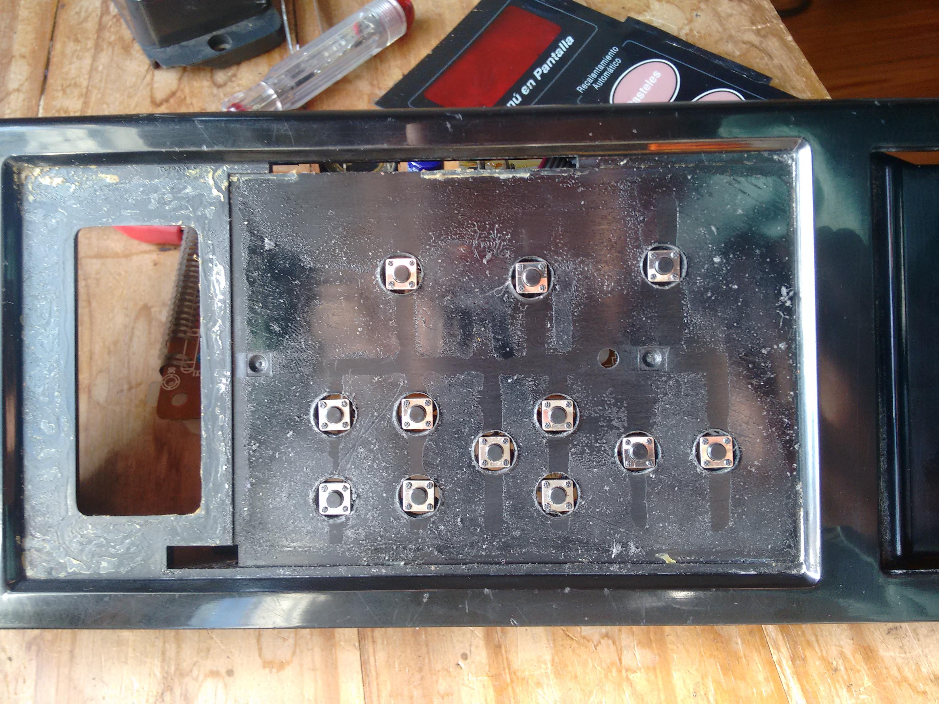
Appears on many places as a “Grove High Temperature Sensor”. It sports an OPA333 precision opamp and a CJ432 adjusted to provide a 1.5V reference. The rest of the circuit is nothing special, except that the manufacturer called the thermistor “light”. It can be consulted here.

First ligths

While I have more capable hardware at hand I grabbed an Arduino Nano and the official library from https://github.com/Seeed-Studio/Grove_HighTemp_Sensor and lo and behold I had it streaming temperature to my terminal.

Let’s get graphical

I cooked a simple gui on python using Qt and Qwt while listening to Olivia Newton.
It is pretty barebones, only has facilities to export into csv, a couple of tracking cursors and gracefully handles device disconnections (say, I yank the cable). I expect to post process the data using QtiPlot or Kst.

Tweaking

One of the first things I noted was that the measured temperature jumped in big steps of about 2°C.
Using the default setup with a 5V “reference” and considering the amplifier gain every adc bit amounts to:

 Vbit = \frac{5000mV}{1023*54.16} = 0.09024 mV

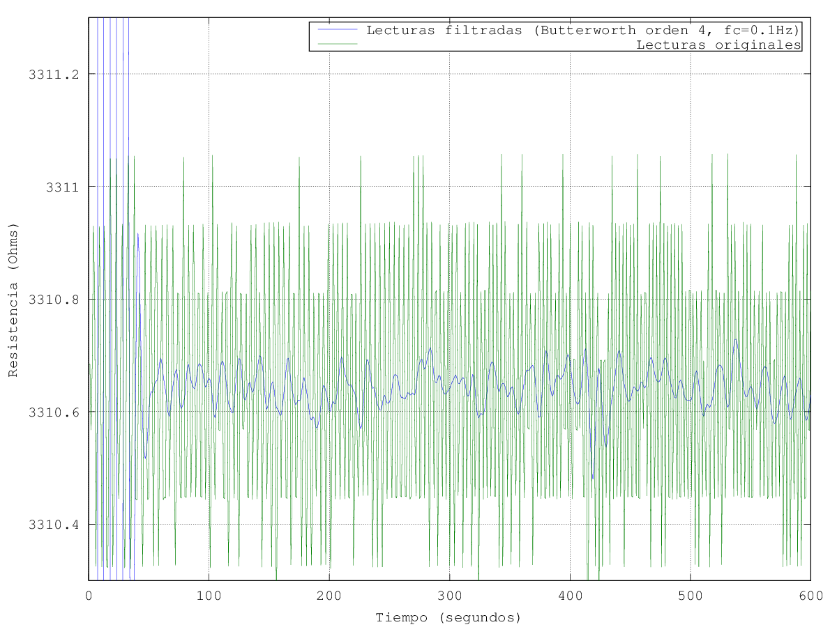
Looking at the polynomial coefficients used by the library (ITS90) and taking a first order approximation one bit corresponds to a 2.26°C step and it grows bigger with the measured temperature as other terms start to influence the result. Even tough the output is low pass filtered at about 1.6KHz and it is averaged over 32 points there’s still noise.

Changing the reference to use the regulated 3.3V makes it about 1.5°C but even if it is more than enough for what I need it can be better.

With a couple of bits more I can achieve better resolution. Instead of using an external adc I took advantage of the inherent noise on the reference and output and chose to apply a 16 times oversample in order to have 12 bits out of the 10 bit adc. Application note AVR121 explains that nicely. Now I am limited (in theory…) to 0.37°C steps and I can average on top of that to further reduce variations.

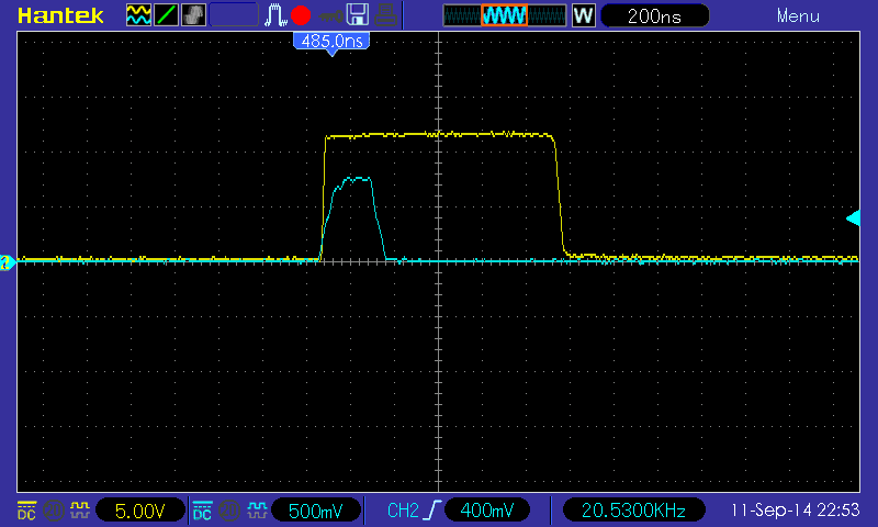
The last source of error (besides not knowing for sure the “real” value of the references) is that the library assumes a fixed 350mV output, the circuit ideally floats the amplified thermocouple voltage around that. In order to measure it I added a small relay from my stash (TQ2SA-5V) to short the input. It is not meant to be used as a dry relay but does fine so far.
Upon startup it reads 348 mV; while a 2mV difference may not seem that big it turns out to be at least 185m°C. Anyway the main sources of error now are the thermocouple and adc reference.

How to make an awesome Android dashboard for your embedded widget

– Use a standard protocol. We chose Firmata.

– Play with nice things. We used Ionic, Apache Cordoba and the wonderful BluetoothSerial plugin.

– Remember to either modify the Firmata firmware to use the default 9600 bps speed of our HC06 adapter or change it to work at 57600.

Browserify a Node implementation of the protocol and make a port-like object so it talks over Bluetooth.

– The bluetooth plugin doesn’t like to work with binary data so we improve it.

After writing some glue code you end up with a nice and working control panel. I only got the working part but there are a ton of cool reusable widgets out there (like NexusUI or KievII)

New life for an old tv tuner.

A long long time ago I bought a cheap pci tuner card to listen to the radio. I was able to watch tv with it out of the box but the radio didn’t work. So I patched the driver and it made it into mainline.

Fast forward today, I don’t have a machine with a pci slot anymore but still wanted to listen to airwaves again as my other stereo broke. So I took out the tuner (a tnf 9835) and cooked a simple pygtk app to control it. I looks just like what you can expect from being born from such a quick hack. After trying for a while to make the hardware i2c interface work I settled for a pure software implementation. (also, pull-ups are not optional) I got all the bit masking ops right the first time (but on the other hand that was just copy pasted from drivers/media/tuners with some small edits). It is basically a nice interface around the SN761677.

Compared with my phone the sensitivity is rather poor as it needs quite a bit of an aerial but the sound quality feels better. Alas, the latter is totally subjective.


Back to basics.

For a course I’m taking at the uni I spent the last weeks programming entirely in assembler for a not very small micro.

Last time I did that for real work was about 12 years ago, dinosaurs roamed the Earth and the 16F84A was popular among my friends here.

It felt quite refreshing but the compiler sometimes behaved like a real jerk.

For instance this was flagged as invalid:

label   db $BA, $DC, $0E

But trimming the spaces made it happy:

label   db $BA,$DC,$0E

(and I spent my weekly cursing budget chasing it)

Fortunately it runs fine under Wine, can be called from a makefile and the debugger/simulator works.

From busted magnetron to incense holder.

It’s been a while since I made something nice.

A couple of weeks ago I spotted a neighbour taking a microwave to the curb and brought it home with me, as they are always full of useful bits. This one was not very old but of a very simple construction. It has a mechanical timer that makes a lovely ‘ding’ when finished. It also went through a bit of hard love.

Cavity magnetrons are very cool devices. Besides providing a couple of strong magnets and aluminum plates they are made of a very pure copper allow with interesting shapes.

From time to time I like to burn some lignum vitae and upon opening this one I knew what to make of it. I chucked it on the drill press, gave it several passes of wet sandpaper and then a cloth with polishing compound. It took quite a good shine but the handling with greasy hands is giving it a light patina. The holes are filled with glow in the dark paint. I haven’t managed yet to capture the effect but they look quite good at night (and also with uv light).

I left the rest without a final polish, partly as a testament of its origins and also because probably I’ll make a cherry wood stand for it.

Adventures in smps carnage I.

A while ago while cleaning the trash pile I thought that it’d be nice to mod one of the many computer supplies to have a variable output. So I picked up the less crappy, replaced the transformer with a one with better turns ratio to achieve a higher voltage output and put a pot on the feedback loop.

At first it kind of worked but with a lot of unstable points and weird modes. Then I realized that I fed the feedback from about 50K when the nominal was near 10K (and also there is considerable input current there). A simple emitter follower took care of that, now there only remains plain oscillations.

The operating point moves a lot considering that I want the output to be adjustable between 5V and 50V and without a fixed load. The original compensation scheme was a plain integrator plus a zero, I can make things a little better slowing it down a lot but what’s the fun on that.

So instead of blindingly doing things I set out to measure the loop response using Middlebrook’s method. I cobbled up a quick python program with Gtk and GStreamer to generate the test signals with a computer soundcard. Initially I expected to just sweep the frequency and measure some points manually on the scope but there is a lot of 50Hz induced interference that together with switching residuals make that task impossible, I really need to perform a synchronous detection in order to get a meaningful result. That means I’ll have to make room for some more quality time coding to get the scope samples in an automated fashion. The usb protocol is documented here ( http://elinux.org/Das_Oszi_Protocol#0x02_Read_sample_data ).

The setup is a far cry from the ones depicted in the famous AN70 by Jim Williams. I used an H-Field probe to rule out magnetics as an interference source. I expected the output filters and the transformer to be troublesome but their effects on the point of injection are negligible. On the other hand, long wires on the feedback path (even twisted) and the snap recovery diodes aren’t a good match.


Isolated trigger output

So I finally added an isolated trigger output to that pulse generator. It is just a gdt from a no brand computer supply driven from another gate so it does not disturb that much the main output. The 100ohm on the secondary it’s there so I don’t forget which are the right leads and that capacitor in parallel with the 1k on the primary is not really needed but it made things nicer with the first transformer I used.

It works as expected:

The ratio is 5V / 0.8V = 0.16 , so that 1k I’ve put on the primary appears as 1k * (0.16^2) = 25.6 Ohm on the other side and matching to 50Ohm is as easy as putting a series resistor.

I already knew that the level shifter has a turn off delay of about 1.3uS compared to the output from the 4093 (look at that, it is 23 years old!). The main contributor to that is the last transistor (a PNP), as I just slapped a 1k resistor from base to emitter and called it a day. On the range of voltages I am interested even if the output latches the dissipation involved is way inside a safe zone, but the cost of that simplicity is that I am not able to bring it into cutoff just as fast. Replacing that with a 220 ohm improves things a bit but it is not the ultimate solution. Anyway, I like it as it is.