Bypassing.

This happens when you forget to add a ‘lytic after the regulator, although the datasheet only shows a 100nF on the output. Not that it really matters on this case. On the pulse generator the logic gates are fed from a regulated supply, mostly so I can forget and use the same as the output stage. Without load and having only a 100nF ceramic halfway between the 7805 and the 4093 (less than a cm…) the rail bounces about 300mVp-p, but it becomes negligible when using a small 10uF in parallel.

Just for kicks I removed the ceramic cap, leaving the output without bypassing at all. The result was a set of narrower 800mVp-p spikes that settled quite fast.

Driver strength.

Last time I made a pulse generator to drive, among other things, some mosfets. When loaded with a gate its rise time increases to about 200ns, trying out some capacitors I get the same result with 5nF. While it is not quite right to approximate the gate with a simple capacitor it helps to ballpark the driver needs.

The output swings 10 volts on 200ns (10%-90% of 12.5 volts) on a 5nF cap. I = C*dV/dt , so 250mA are flowing. If I want a faster driver I’ll need to add another stage, as the BC548 won’t give me much more current. LTSpice kind of agrees with these numbers, but I need to put 15nF to match the rise time (and the current increases accordingly).

Inductor saturation tester

“You have a quite novel approach to high current circuits”

(This is one in a series of posts, not in chronological order.)
Lately I’ve been playing again with switched supplies. The last time I worked mostly blind, not having a scope I sampled the available inductors around my needed values and settled with the ones that didn’t catch fire for the first test run.

Now I wanted to try more topologies, and having a lot of unknown cores, I needed to characterize them. I started with the traditional BH measurement using a small ac source and an integrator. I haven’t got round to finish the writeup on that one but it gave me some useful data to start.

Still, I needed to measure with more precision their inductance and how they behave when handling high currents. I lashed up a pulse generator with variable on period using  a couple of schmit trigger gates and a level shifter. When loaded by the gate the risetime goes from about 20ns to 200ns, there’s room for improvement considering it was made from parts I had lying around and without too much thought. I can also lower the drive voltage, above 6 volts the gate charge increases. Meanwhile, I’ll need to add an isolated trigger output.

The power section is comprised of an irf540, a medium value shunt, flyback diode, some local decoupling and a snubber. I’m using high side sensing as it lets me monitor the current and voltage on the dut easily without resorting to differential probes. Also the fet’s source won’t rise above ground when using the same supply for both the driver and power stage, sparing me from a whole lot of problems. The shunt is made with two 0.22 ohm resistors of dubious quality in parallel. While I have a couple of 50 mohm ones made just for that for most of the time the resulting voltage will be too low to work comfortably. It doesn’t look good but gets the job done (the power section was made with parts from another test fixture, so there are some leftovers).

Shorting the test leads I get this:

Plugging in all the constants the fixture has a stray inductance of about 2.1 uH. ( V/L = dI / dT , all that can be read off the cursors ). On the linear part, the average current is 25 amps, so the resistance turns out to be close to 0.4 ohms. Looking at the power input it dips around 2 volts (not that bad being it a cheap pc supply) and then overshoots by 6 volts. However, looking at the connectors on the far end it is not that bad:

So, most of the voltage drop and artefacts are due to poor local decoupling, long leads and connector resistance. That funny ringing on the drive signal is because the scope ground is just at the supply terminals and it bounces a lot given that there are about 30cm of leads in between.

After tidying things a bit and putting the snubber and flyback where they are supposed to be it works like a charm:

Redid some of the shots, so their dates don’t match anymore.

The root of all evil.

I just love when I forget to add ‘volatile’ and the compiler happily optimizes away a chunk of code.

After staring for a while at the screen trying to figure out why it doesn’t work as expected I went for a quick nap. When I got back I noticed several warnings about it that were invisible to my eyes before.

Using WebKitGTK as the UI for GStreamer applications.

Lately I’ve been thinking a lot about how can I make nice and easily customizable interfaces for video applications. My idea of ‘nice’ is kind of orthogonal to what most of my expected user base will want, and by ‘easily customizable’ I don’t mean ‘go edit this glade file / json stage / etc’.

Clutter and MX are great to make good looking interfaces and like Gtk have something that resembles css to style stuff and can load an ui from an xml or json file. However, they will need sooner or later a mix developer and a designer. And unless you do something up front, the interface is tied to the backend process that does the heavy video work.

So, seeing all the good stuff we are doing with Caspa, the VideoEditor, WebVfx and our new magical synchronization framework I questioned:

Why instead of using Gtk, can’t I make my ui with html and all the fancy things that are already made?

And while we are at it I want process isolation, so if the ui crashes (or I want to launch more than one to see side by side different ui styles) the video processing does not stop. Of course, should I want more tightly coupling I can embed WebKit on my application and make a javascript bridge to avoid having to use something like websockets to interact.

One can always dream…

Then my muse appeared and commanded me to type. Thankfully, mine is not like the poor soul on “Blank Page” had.

So I type, and I type, and I type.

‘Till I made this: two GStreamer pipelines, outputting to auto audio and video sinks and also to a webkit process. Buffers travel thru shared memory, still they are copied more than I’d like to but that makes things a bit easier and helps decoupling the processes, so if one stalls the others don’t care (and anyway for most of the things I want to do I’ll need to make a few copies). Lucky me I can throw beefier hardware and play with more interesting things.

I expect to release this in a couple of weeks when it’s more stable and usable, as of today it tends to crash if you stare at it a bit harder.

“It’s an act of faith, baby”
Using WebKit to display video from a GStreamer application.

Using WebKit to display video from a GStreamer application.
Something free to whoever knows who the singer is without using image search.


Nerd weekend.

So last week I gifted myself an arm linux system with a very fast soundcard. Or a 100MHz digital oscilloscope, as they are quite the same.

A while ago I made a current sink that has served me well for testing dumb power supplies and anodizing stuff. For mostly resistive loads it behaves well, however as soon as you try to load something with small resistance and some inductance (like the head coils of an IBM3390 disk or a very stiff smps without a resistor to dissipate most of the power) it starts to oscillate.

Possessing this new gadget and a cold I decided to spend the weekend tackling this problem. I started by making another one on a breadboard and feeding back the current sense with a four terminal setup. That was quite an improvement over the original, among many mistakes I used a ground pour and despite the high current loop being very small and near the binding posts the ground potential differed by a not insignificant amount between points on the board.

The only power supply I had was a not very bad ATX one from a former desktop. It’s beefy and I can attest that the current limit and short circuit protections do work. The only downside is that it is really noisy, about 100mV p-p on the 12V rail with a 2A load and it gets worse from there, mostly from the conmutation and some hf hash. So the first thing I did was to improvise a couple of regulators with a low pass filter and a series pass transistor. After that it went down to 2mV p-p, rejection is not that great but will do.

My initial intentions were to approach the problem from a control system point but even for a quite trivial circuit like this one the modelling becomes convoluted once you add stuff like the feedback from collector to base on the output transistor, the dependence of the small signal gain and CE capacitance with the operating point or the interactions between power supplies. And most of them have influence on the oscillatory behaviour with extreme loads.

So I gave a full turn and started with a more practical solution. One of the first things to improve stability is to reduce gain or at least roll off at high frequencies. I replaced the original feedback loop with a 10K pot, wiper goes to the inverting input, one side to the opamp output with a 100n cap and the other to the sense resistor. Then, with a problematic inductor, I slowly rised the current setpoint until it started to oscillate; moving the wiper closer to the output made it stop. This has to be repeated a couple of times, as there are many unstable points. The only drawback of this approach is that the corner frequecy is fixed and you only end up changing the gain, and as such there can still be a lot of unstable operation points.

After that I continued by adding a snubber network from ground to the collector, effectively bypassing the control loop. There are many recipes for when you know with more or less accuracy the parameters of the tank circuit but in this case all I knew was that the output capacitance of the TIP122 was on the order of 200p and most of the things I am interested on have inductances from some uH to many mH. I  had a 1uF mica and a 2.7Ohm power resistor at hand and gave them a go. Bam! all the oscillations were gone.

But what happened to the dynamic response of the system?

The snubber network had no visible effect. On the other hand the naive compensation worsened the disturbance rejection. The arrangement with a potentiometer has the side effect of behaving like a low pass filter for the signal that comes from the sense resistor, thus increasing the response time, as can be seen on the following pictures (the glitchy stuff is because I just shorted the  load with an alligator clip).

While I’m mostly happy because the dummy load has improved I still feel like a hack because solving the problem from a more analytical standpoint turned out to be more difficult than what I expected. However, if I consider that I made every possible mistake on the initial design and this testbench stabilizing it was quite a feat (just a copper pour for the groundplane, power and signal grounds mixed, loops, long cables, etc).

So far I made three mathematical models that kind of satisfy me but every one explains part of the observed behaviour and involve some unnerving hand waving and simplifications. I will upload them soon.

That thrill.

Lately I’ve been working with a lot of technologies that are a bit outside of my comfort zone of hardware and low level stuff. Javascript, html-y things and node.js.  At first it was a tad difficult to wrap my head around all that asynchronism and things like hoisting and what is the value of ‘this’ here. And inheritance.

Then, out of a sudden I had an epiphany and I wrote a truly marvellous piece of software. Now I can use Backbone.io on the browser and the server, the same models and codebase on both without a single change. Models are automatically synchronized. On top of that there’s a redis transport so I can sync models between different node instances in real time without hitting the storage (mongo in this case). And the icing of the cake is that a python compatibility module is about to come.

The bragging tax.

This is no news but I don’t get people. I really don’t.

When a potential client approached me for a quote normally I gave two estimates. One if I am allowed to write something about it and another one (substantially higher) if they refuse.

I never said a word about open sourcing it, naming names or something like that.

Most of the time I explain, as politely as I can, that nobody is going to ‘steal’ they wonderful idea. And also that it is just a very simple variation on stuff found on textbooks and, the only original thing they did was to put a company logo on it.

It is such a shame that I honour my word in these cases.

Modifying microphone directivity.

So, we have some Logitech C920 cameras. They are really good for their price and sport a couple of microphones with echo cancellation and an omnidirectional pattern. Which is quite great for its intended use but a major pain if what you want to perform voice activity detection. Basically, all the cameras trigger when someone speaks. It can be worked around but things are a lot easier when the sound from one camera doesn’t leak that much into the others.

Not wanting to replace or modify the internal microphone array if there was another way I decided to test if with some absorbent foam the response could be shaped to something more useful.

Utilísima un poroto.

I cut a couple of rectangular prisms with cavities that more or less match the shape of the cameras. My supply of plushy fabric was rather limited and so I planned a bit more carefully how to divide it and make the crevices. After that I just cut it in four equal pieces and held everything with hot melt glue and some stitches.

Results.

I don’t have proper facilities like an anechoic chamber. Testing was done using a 1KHz tone and recording the sound from the back, 45 and 90 degrees ccw (shouldn’t matter) and facing the front of the camera. While there’s an improvement over the original pattern, the directivity achieved is not enough so we’ll pursue an alternate way of capturing sound (either a multichannel soundcard or modifying the internal mics).

On GStreamer performance with multiple sources.

I’ve made a couple of experiments with Tetra. Right now the code that manages disconnection of live sources (say, someone pulls the cable and walks away with one of our cameras) kind of works, it certainly does on my system but with differnet sets of libraries sometimes the main gst pipeline just hangs there and it really bothers me that I’m unable to get it right.

So I decided to really split it on a core that does the mixing (either manually or automatic) and different pipelines that feed it. Previously I had success using the inter elements (with interaudiosrc hacked so its latency is acceptable) to have another pipeline with video from a file mixed with live content.

Using the inter elements and a dedicated pipeline for each camera worked fine, the camera pipeline could die or dissapear and the mixing pipeline churned happily. The only downside is that it puts some requirements on the audio and video formats.

Something that I wasn’t expecting was that cpu utilization lowered, before I had two threads using 100% and 30% (and many others below 10%) of cpu time and both cores on average at 80% load. With different pipelines linked with inter elements I had two threads, one at 55% and a couple of others near 10%; both cores a tad below 70%.

Using shmsrc / shmsink yielded similar performance results but as a downside it behaved just like the original regarding the sources being disconnected, so for now I’m not considering them to ingest video. On the other hand latency was imperceptible as expected.

Using the Gstreamer Controller subsystem from Python.

This is more or less a direct translation of the examples found at gstreamer/tests/examples/controller/*.c to their equivalents using the gi bindings for Gstreamer under Python. The documentation can be found here. Reading the source also helps a lot.

The basic premise is that you can attach a controller to almost any property of an object, set an interpolation function and give it pairs of (time, value) so they are smoothly changed. I’m using a pad as a target instead of an element just because it fits my immediate needs but it really can be any Element.

First you need to import Gstreamer and initialize it:

#!/usr/bin/python
import gi
import sys
from gi.repository import GObject
gi.require_version('Gst', '1.0')
from gi.repository import Gst
from gi.repository import GstController
from gi.repository import Gtk
from gi.repository import GLib

GObject.threads_init()
Gst.init(sys.argv)

Then create your elements. This is by no means the best way but lets me cut a bit on all the boilerplate.


p = Gst.parse_launch ("""videomixer name=mix ! videoconvert ! xvimagesink
videotestsrc pattern="snow" ! videoconvert ! mix.sink_0
videotestsrc ! videoconvert ! mix.sink_1
""")

m = p.get_by_name ("mix")
s0 = [pad for pad in m.pads if pad.name == 'sink_0'][0]
s0.set_property ("xpos", 100)

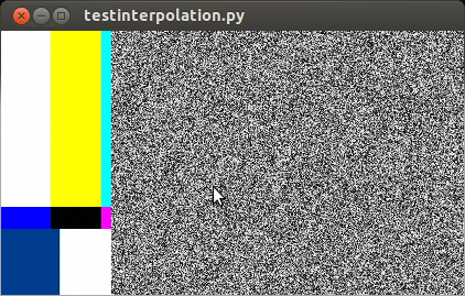
Here I created two test sources, one with bars and another with static that also has an horizontal offset. If we were to start the pipeline right now ( p.set_state (Gst.State.PLAYING) ) we would see something like this:

captura_testinterpolation

So far it works. Now I’d like to animate the alpha property of s0 (the sink pads of a videomixer have interesting properties like alpha, zorder, xpos and ypos). First we create a control source and set the interpolation mode:

cs = GstController.InterpolationControlSource()
cs.set_property('mode', GstController.InterpolationMode.LINEAR)

Then we create a control binding for the property we want to animate and add it to our element:

cb = GstController.DirectControlBinding.new(s0, 'alpha', cs)
s0.add_control_binding(cb)

It is worth noting that the same control source can be used with more than one control binding.

Now we just need to add a couple of points and play:

cs.set(0*Gst.SECOND, 1)
cs.set(4*Gst.SECOND, 0.5)
p.set_state (Gst.State.PLAYING)

If you are not running this from the interpreter remember to add GObject.MainLoop().run() , otherwise the script will end instead of keep playing. Here I’ve used absolute times, to animate in the middle of a playing state you need to get the current time and set the points accordingly, something like this will do most of the cases:


start = p.get_clock().get_time() # XXX: you better check for errors
end = start + endtime*Gst.SECOND

Avoiding too much bookkeeping

You can get the controller and control source of an element with:

control_binding = element.get_control_binding('property')
if control_binding:
    control_source = control_binding.get_property('control_source')