Adventures in smps carnage I.

A while ago while cleaning the trash pile I thought that it’d be nice to mod one of the many computer supplies to have a variable output. So I picked up the less crappy, replaced the transformer with a one with better turns ratio to achieve a higher voltage output and put a pot on the feedback loop.

At first it kind of worked but with a lot of unstable points and weird modes. Then I realized that I fed the feedback from about 50K when the nominal was near 10K (and also there is considerable input current there). A simple emitter follower took care of that, now there only remains plain oscillations.

The operating point moves a lot considering that I want the output to be adjustable between 5V and 50V and without a fixed load. The original compensation scheme was a plain integrator plus a zero, I can make things a little better slowing it down a lot but what’s the fun on that.

So instead of blindingly doing things I set out to measure the loop response using Middlebrook’s method. I cobbled up a quick python program with Gtk and GStreamer to generate the test signals with a computer soundcard. Initially I expected to just sweep the frequency and measure some points manually on the scope but there is a lot of 50Hz induced interference that together with switching residuals make that task impossible, I really need to perform a synchronous detection in order to get a meaningful result. That means I’ll have to make room for some more quality time coding to get the scope samples in an automated fashion. The usb protocol is documented here ( http://elinux.org/Das_Oszi_Protocol#0x02_Read_sample_data ).

The setup is a far cry from the ones depicted in the famous AN70 by Jim Williams. I used an H-Field probe to rule out magnetics as an interference source. I expected the output filters and the transformer to be troublesome but their effects on the point of injection are negligible. On the other hand, long wires on the feedback path (even twisted) and the snap recovery diodes aren’t a good match.


Isolated trigger output

So I finally added an isolated trigger output to that pulse generator. It is just a gdt from a no brand computer supply driven from another gate so it does not disturb that much the main output. The 100ohm on the secondary it’s there so I don’t forget which are the right leads and that capacitor in parallel with the 1k on the primary is not really needed but it made things nicer with the first transformer I used.

It works as expected:

The ratio is 5V / 0.8V = 0.16 , so that 1k I’ve put on the primary appears as 1k * (0.16^2) = 25.6 Ohm on the other side and matching to 50Ohm is as easy as putting a series resistor.

I already knew that the level shifter has a turn off delay of about 1.3uS compared to the output from the 4093 (look at that, it is 23 years old!). The main contributor to that is the last transistor (a PNP), as I just slapped a 1k resistor from base to emitter and called it a day. On the range of voltages I am interested even if the output latches the dissipation involved is way inside a safe zone, but the cost of that simplicity is that I am not able to bring it into cutoff just as fast. Replacing that with a 220 ohm improves things a bit but it is not the ultimate solution. Anyway, I like it as it is.

Bypassing.

This happens when you forget to add a ‘lytic after the regulator, although the datasheet only shows a 100nF on the output. Not that it really matters on this case. On the pulse generator the logic gates are fed from a regulated supply, mostly so I can forget and use the same as the output stage. Without load and having only a 100nF ceramic halfway between the 7805 and the 4093 (less than a cm…) the rail bounces about 300mVp-p, but it becomes negligible when using a small 10uF in parallel.

Just for kicks I removed the ceramic cap, leaving the output without bypassing at all. The result was a set of narrower 800mVp-p spikes that settled quite fast.

Inductor saturation tester

“You have a quite novel approach to high current circuits”

(This is one in a series of posts, not in chronological order.)
Lately I’ve been playing again with switched supplies. The last time I worked mostly blind, not having a scope I sampled the available inductors around my needed values and settled with the ones that didn’t catch fire for the first test run.

Now I wanted to try more topologies, and having a lot of unknown cores, I needed to characterize them. I started with the traditional BH measurement using a small ac source and an integrator. I haven’t got round to finish the writeup on that one but it gave me some useful data to start.

Still, I needed to measure with more precision their inductance and how they behave when handling high currents. I lashed up a pulse generator with variable on period using  a couple of schmit trigger gates and a level shifter. When loaded by the gate the risetime goes from about 20ns to 200ns, there’s room for improvement considering it was made from parts I had lying around and without too much thought. I can also lower the drive voltage, above 6 volts the gate charge increases. Meanwhile, I’ll need to add an isolated trigger output.

The power section is comprised of an irf540, a medium value shunt, flyback diode, some local decoupling and a snubber. I’m using high side sensing as it lets me monitor the current and voltage on the dut easily without resorting to differential probes. Also the fet’s source won’t rise above ground when using the same supply for both the driver and power stage, sparing me from a whole lot of problems. The shunt is made with two 0.22 ohm resistors of dubious quality in parallel. While I have a couple of 50 mohm ones made just for that for most of the time the resulting voltage will be too low to work comfortably. It doesn’t look good but gets the job done (the power section was made with parts from another test fixture, so there are some leftovers).

Shorting the test leads I get this:

Plugging in all the constants the fixture has a stray inductance of about 2.1 uH. ( V/L = dI / dT , all that can be read off the cursors ). On the linear part, the average current is 25 amps, so the resistance turns out to be close to 0.4 ohms. Looking at the power input it dips around 2 volts (not that bad being it a cheap pc supply) and then overshoots by 6 volts. However, looking at the connectors on the far end it is not that bad:

So, most of the voltage drop and artefacts are due to poor local decoupling, long leads and connector resistance. That funny ringing on the drive signal is because the scope ground is just at the supply terminals and it bounces a lot given that there are about 30cm of leads in between.

After tidying things a bit and putting the snubber and flyback where they are supposed to be it works like a charm:

Redid some of the shots, so their dates don’t match anymore.

The root of all evil.

I just love when I forget to add ‘volatile’ and the compiler happily optimizes away a chunk of code.

After staring for a while at the screen trying to figure out why it doesn’t work as expected I went for a quick nap. When I got back I noticed several warnings about it that were invisible to my eyes before.

Using WebKitGTK as the UI for GStreamer applications.

Lately I’ve been thinking a lot about how can I make nice and easily customizable interfaces for video applications. My idea of ‘nice’ is kind of orthogonal to what most of my expected user base will want, and by ‘easily customizable’ I don’t mean ‘go edit this glade file / json stage / etc’.

Clutter and MX are great to make good looking interfaces and like Gtk have something that resembles css to style stuff and can load an ui from an xml or json file. However, they will need sooner or later a mix developer and a designer. And unless you do something up front, the interface is tied to the backend process that does the heavy video work.

So, seeing all the good stuff we are doing with Caspa, the VideoEditor, WebVfx and our new magical synchronization framework I questioned:

Why instead of using Gtk, can’t I make my ui with html and all the fancy things that are already made?

And while we are at it I want process isolation, so if the ui crashes (or I want to launch more than one to see side by side different ui styles) the video processing does not stop. Of course, should I want more tightly coupling I can embed WebKit on my application and make a javascript bridge to avoid having to use something like websockets to interact.

One can always dream…

Then my muse appeared and commanded me to type. Thankfully, mine is not like the poor soul on “Blank Page” had.

So I type, and I type, and I type.

‘Till I made this: two GStreamer pipelines, outputting to auto audio and video sinks and also to a webkit process. Buffers travel thru shared memory, still they are copied more than I’d like to but that makes things a bit easier and helps decoupling the processes, so if one stalls the others don’t care (and anyway for most of the things I want to do I’ll need to make a few copies). Lucky me I can throw beefier hardware and play with more interesting things.

I expect to release this in a couple of weeks when it’s more stable and usable, as of today it tends to crash if you stare at it a bit harder.

“It’s an act of faith, baby”
Using WebKit to display video from a GStreamer application.

Using WebKit to display video from a GStreamer application.
Something free to whoever knows who the singer is without using image search.


Nerd weekend.

So last week I gifted myself an arm linux system with a very fast soundcard. Or a 100MHz digital oscilloscope, as they are quite the same.

A while ago I made a current sink that has served me well for testing dumb power supplies and anodizing stuff. For mostly resistive loads it behaves well, however as soon as you try to load something with small resistance and some inductance (like the head coils of an IBM3390 disk or a very stiff smps without a resistor to dissipate most of the power) it starts to oscillate.

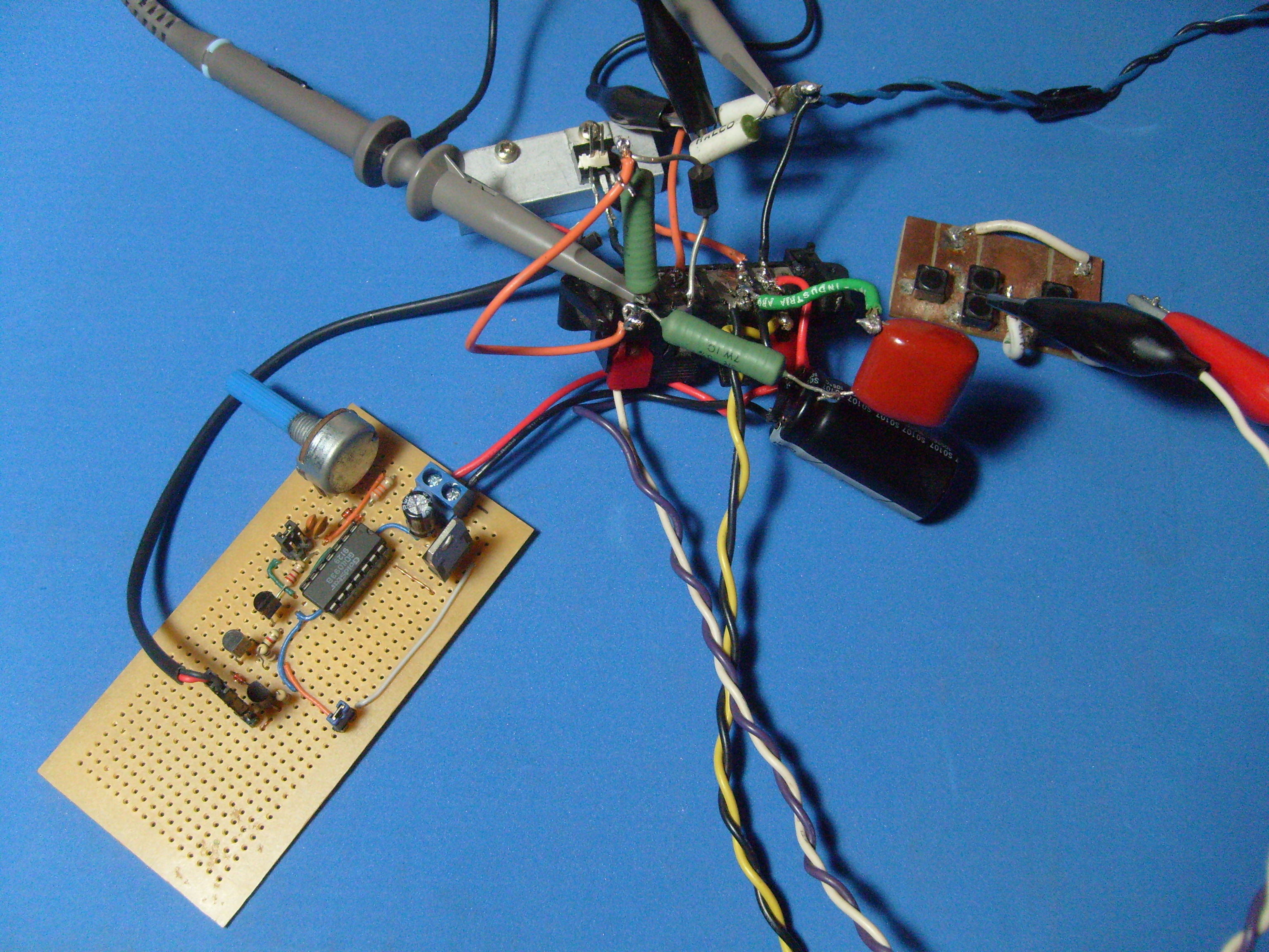
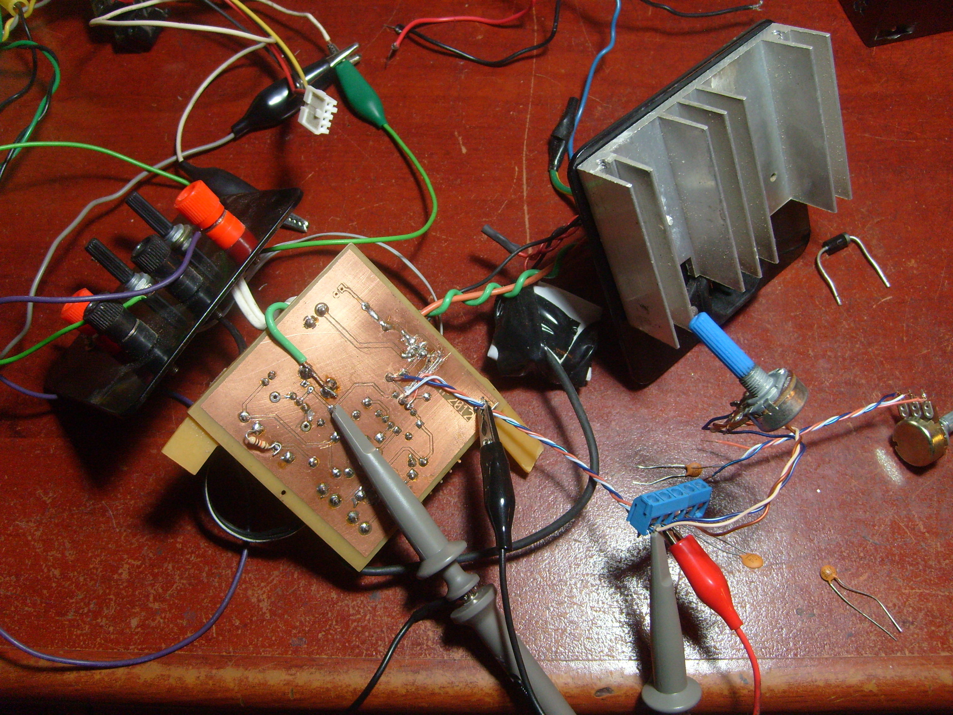
Possessing this new gadget and a cold I decided to spend the weekend tackling this problem. I started by making another one on a breadboard and feeding back the current sense with a four terminal setup. That was quite an improvement over the original, among many mistakes I used a ground pour and despite the high current loop being very small and near the binding posts the ground potential differed by a not insignificant amount between points on the board.

The only power supply I had was a not very bad ATX one from a former desktop. It’s beefy and I can attest that the current limit and short circuit protections do work. The only downside is that it is really noisy, about 100mV p-p on the 12V rail with a 2A load and it gets worse from there, mostly from the conmutation and some hf hash. So the first thing I did was to improvise a couple of regulators with a low pass filter and a series pass transistor. After that it went down to 2mV p-p, rejection is not that great but will do.

My initial intentions were to approach the problem from a control system point but even for a quite trivial circuit like this one the modelling becomes convoluted once you add stuff like the feedback from collector to base on the output transistor, the dependence of the small signal gain and CE capacitance with the operating point or the interactions between power supplies. And most of them have influence on the oscillatory behaviour with extreme loads.

So I gave a full turn and started with a more practical solution. One of the first things to improve stability is to reduce gain or at least roll off at high frequencies. I replaced the original feedback loop with a 10K pot, wiper goes to the inverting input, one side to the opamp output with a 100n cap and the other to the sense resistor. Then, with a problematic inductor, I slowly rised the current setpoint until it started to oscillate; moving the wiper closer to the output made it stop. This has to be repeated a couple of times, as there are many unstable points. The only drawback of this approach is that the corner frequecy is fixed and you only end up changing the gain, and as such there can still be a lot of unstable operation points.

After that I continued by adding a snubber network from ground to the collector, effectively bypassing the control loop. There are many recipes for when you know with more or less accuracy the parameters of the tank circuit but in this case all I knew was that the output capacitance of the TIP122 was on the order of 200p and most of the things I am interested on have inductances from some uH to many mH. I  had a 1uF mica and a 2.7Ohm power resistor at hand and gave them a go. Bam! all the oscillations were gone.

But what happened to the dynamic response of the system?

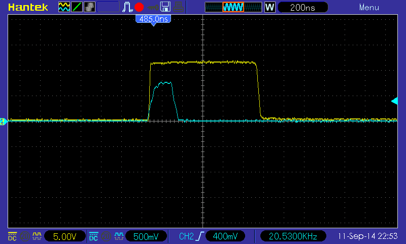
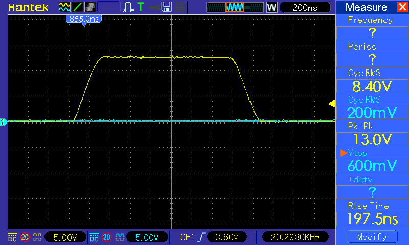
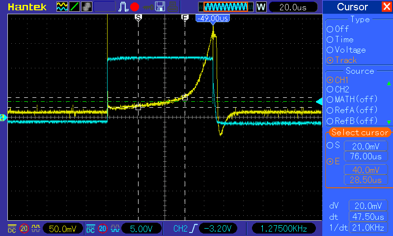
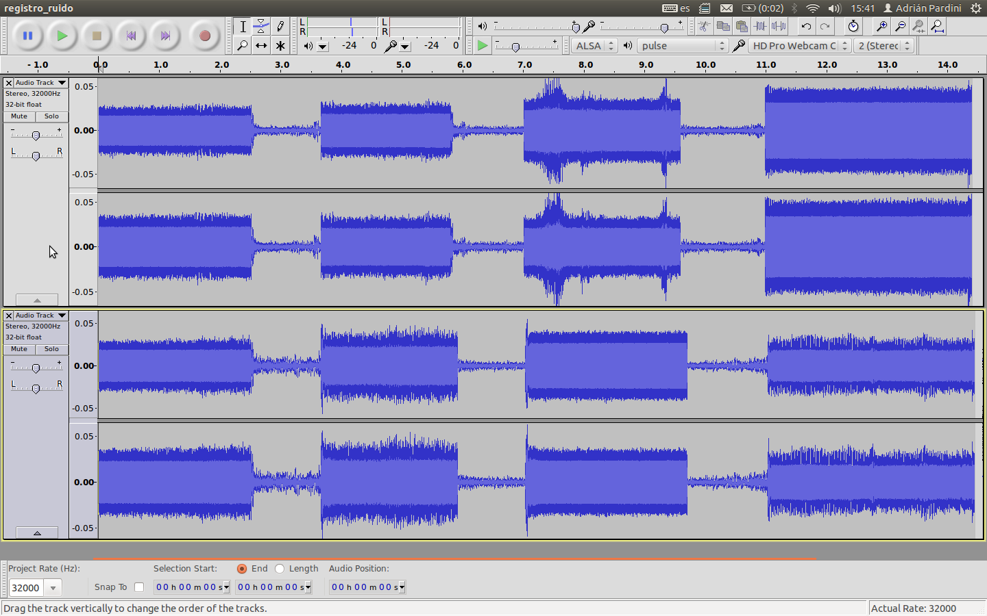
The snubber network had no visible effect. On the other hand the naive compensation worsened the disturbance rejection. The arrangement with a potentiometer has the side effect of behaving like a low pass filter for the signal that comes from the sense resistor, thus increasing the response time, as can be seen on the following pictures (the glitchy stuff is because I just shorted the  load with an alligator clip).

While I’m mostly happy because the dummy load has improved I still feel like a hack because solving the problem from a more analytical standpoint turned out to be more difficult than what I expected. However, if I consider that I made every possible mistake on the initial design and this testbench stabilizing it was quite a feat (just a copper pour for the groundplane, power and signal grounds mixed, loops, long cables, etc).

So far I made three mathematical models that kind of satisfy me but every one explains part of the observed behaviour and involve some unnerving hand waving and simplifications. I will upload them soon.

Modifying microphone directivity.

So, we have some Logitech C920 cameras. They are really good for their price and sport a couple of microphones with echo cancellation and an omnidirectional pattern. Which is quite great for its intended use but a major pain if what you want to perform voice activity detection. Basically, all the cameras trigger when someone speaks. It can be worked around but things are a lot easier when the sound from one camera doesn’t leak that much into the others.

Not wanting to replace or modify the internal microphone array if there was another way I decided to test if with some absorbent foam the response could be shaped to something more useful.

Utilísima un poroto.

I cut a couple of rectangular prisms with cavities that more or less match the shape of the cameras. My supply of plushy fabric was rather limited and so I planned a bit more carefully how to divide it and make the crevices. After that I just cut it in four equal pieces and held everything with hot melt glue and some stitches.

Results.

I don’t have proper facilities like an anechoic chamber. Testing was done using a 1KHz tone and recording the sound from the back, 45 and 90 degrees ccw (shouldn’t matter) and facing the front of the camera. While there’s an improvement over the original pattern, the directivity achieved is not enough so we’ll pursue an alternate way of capturing sound (either a multichannel soundcard or modifying the internal mics).

Debugging USB3.0 issues when dealing with USB2.0 devices

Some time ago we needed to connect as many usb cameras as possible to a single computer and capture full hd video and audio. Most of our systems despite having a lot of connectors on the inside they really have one host controller and a hub.

While the available bandwidth may be more than enough using a compressed format the amount of isochronous transfers is rather limited. Our minimal use case called for three C920 cameras. On a normal system (one host controller behind a hub) the best we could achieve was two at 1280×720@30fps with audio and a third without audio, and only one at 1920×1080@30fps with audio.

So, we need to add more controllers. Usb 2.0 add-on cards are a thing of the past but luckily they were replaced with the faster USB3. Most of the usb 3 controllers also feature an usb 2.0 controller and hub for older devices but some (very rare) have a dedicated usb 2 controller for each port.

Given this I went ahead and bought two cards of different brand and different chipset each.

One of them had a NEC PD720200. It worked like a charm but sadly only has one usb 2 controller.

The other sported a VIA VL800. This one has one usb 2 controller per port (this can be seen with lsub -t). That lovingly discovering didn’t last for too long as the controller crashed all the time, at best it would stop responding but sometimes it locked my system hard. The guys at Via have a very interesting definition of meeting the specs. I’ve spent a whole weekend patching kernels trying to make it behave. Now I have a quite expensive and sophisticated paperweight.

Testing procedures:

I ssh’d to the target machine and ran in several consoles:

watch -n1 ‘dmesg | tail -n 16’ to have a log should the system crash hard.

watch -n1 ‘grep Alloc /sys/kernel/debug/usb/devices’ to monitor bus usage.

– 3x gst-launch-1.0 v4l2src device=[camera] ! queue ! ! fakesink sync=true alsasrc device=[camera soundcard] ! queue ! fakesink sync=true to capture from each device. video_caps is something like “image/jpeg,width=1920,height=1080,framerate=30/1” but I tried a couple more.

It is really wonderful how much computing power we have nowadays. The first time I compiled a kernel it took a good four hours. On my current machine (not quite new…) it takes about forty minutes from a clean tree and around ten from an already compiled one.

debugging_usb3-0

Hoy programo porque estoy deprimido.

Hoy programo, un módulo para MLT Framework que permite vincular varias instancias de melt usando el mismo protocolo que shmsink / shmsrc de GStreamer. Un plugin para ingresar material de melt en un pipeline de gst.

Descubrí que hace rato no tengo el área del cerebro para entender multithreading. Descubrí que todos los frameworks / librerías de vídeo en su interior albergan los mas oscuros y horribles secretos (aunque algunas no se esfuerzan en ocultarlos mucho). Por suerte el hardware es barato, no sé por qué me esfuerzo en hacer algo zerocopy si total vos lo vas a copiar de gusto cuatro o cinco veces.